It seems to me that today it is difficult to buy an inexpensive HOn3 locomotive. The excellent Blackstone Models K-27 and C-19 are often listed at multiples of their original MSRP. Looking to the brass market, the used models are commanding two and three times the prices they did a few years ago, and thousand dollar price tags are becoming common. To top it off, it’s been a decade or more since Model Die Casting stopped making their inexpensive HOn3 locomotive kits and un-built versions of these kits are rare. Division Point is the last brass importer in HOn3, but their exquisite models are in the $2000.00 range. I can’t help but think how overwhelming it must be for someone on a budget who wants to get into HOn3.
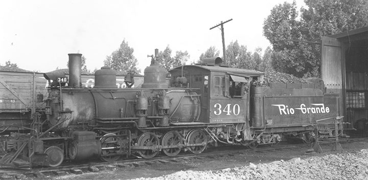
This photo shows D&RGW #340 in the late 1940s. I chose to model it in a slightly earlier era, and left off a few details like the Priest flanger and cab curtains.
However, there are locomotives out there if you don’t mind doing a little research. Many older models occasionally come up for sale at a reasonable price. They are often discounted because they lack details, open frame motors, and DCC features that are common in more modern models. All of these shortcomings can easily be overcome. There are also used models that come on the market that may have terrible paint jobs, or need minor repairs. At first it may seem overwhelming to take on one of these locomotives, but if you take it a step at a time, it’s really not that hard. And when you reach the finish line, it’s incredibly rewarding, and fun, to turn what was a substandard model into a real jewel.
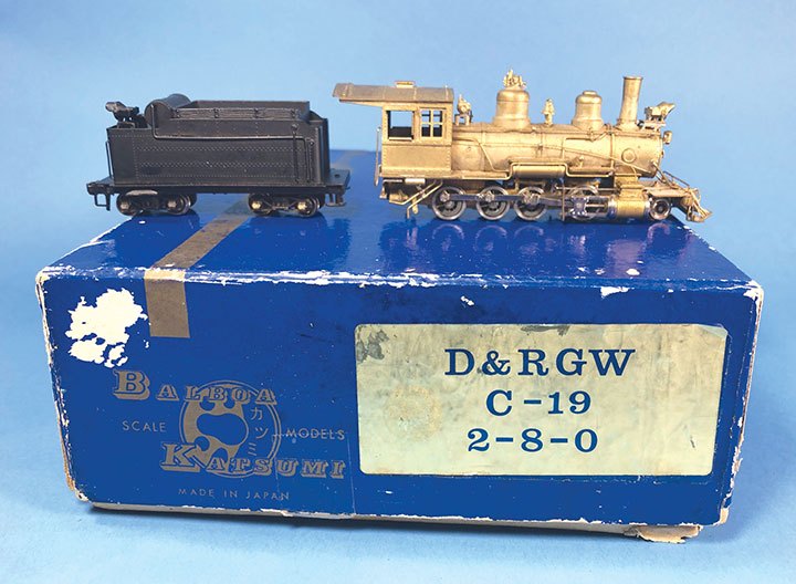
I bought this model off eBay. It was partly assembled and partly painted. I could tell by the photos that it was missing some common fasteners, but all of the difficult to find parts were there. The model fit my criteria for being a great candidate for this brass-bashing project.
I’ve written a few brass bashing articles for the Gazette in the past, but my latest observations of the lack of HOn3 locomotives has inspired me to write this article and maybe more. No, I don’t own sophisticated tools like a lathe or milling machine, and don’t even own a decent resistance soldering setup. Most of my brass bashing is done with simple, inexpensive hand tools that most modelers should have. In the May/June 2017 Gazette, I described the tools I use. The one thing I do have, that most modelers don’t, is a sizeable collection of brass stock, micro fasteners, motors and detail parts. Most of these are left over from previous projects, or from purchasing more parts than I needed. The biggest advantage of my collection is that I can try many options as I navigate through a brass-bashing project.
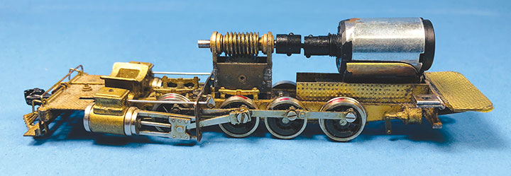
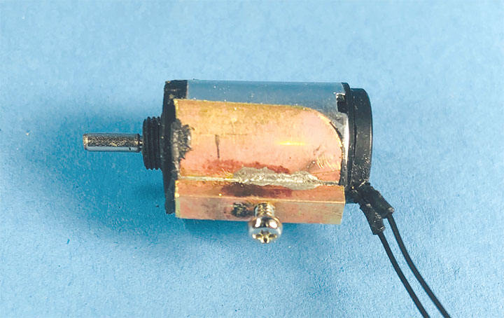
I like to run all my locomotives, so I start by coming up with a plan for the drive train. In HOn3, there are not a lot of options for replacement gearboxes, so I like to re-use as much as possible. In the case of this model, the gearbox was in good shape and it ran well. However, the huge open frame motor had to go. I went to my supply of motors and tried a few. As I compared the motors, I thought about motor placement, how I’d connect it to the gearbox, and if it would all fit inside the boiler. Because I wanted to hide the motor, it needed to be smaller than the diameter of the boiler, and be short enough to not protrude from the back of the cab. I also needed to figure out how I was going to couple it to the gearbox. Using a piece of rubber tube to temporarily connect my motor candidates to the gearbox, I fit and ran each motor to see if it was suitable. I ended up choosing a 13mm x 20mm Maxon coreless motor that I had purchased on eBay. Because the gearbox was solidly attached to the frame and not floating on the drive axle like most models, I created a universal jointed driveshaft from Northwest Short Line parts. If it had a floating gearbox, I could have used a torque arm to join the motor to the gearbox, or used rubber tubing to make the connection. I would have preferred that the universal joint couplings were in a straight line, but the slight offset was needed to get the motor to fit inside the boiler. It’s not ideal, but the beauty of universal joints is that they will compensate for this.
For this article I’m going to take you step by step through upgrading a fifty-year-old Balboa HOn3 model of a D&RGW C-19 class 2-8-0. This is a project that I’ve planned to do for a long time. This Balboa model is a great stand-in for D&RGW #340. Except for the expensive, beautifully detailed, yet marginally running models put out by Precision Scale over a decade ago, there were no other commercially available models of #340. Its distinctive features were even left off in the run of Blackstone C-19s that were put out years ago. Since the prototype was often leased to the Rio Grande Southern, I had to have one.
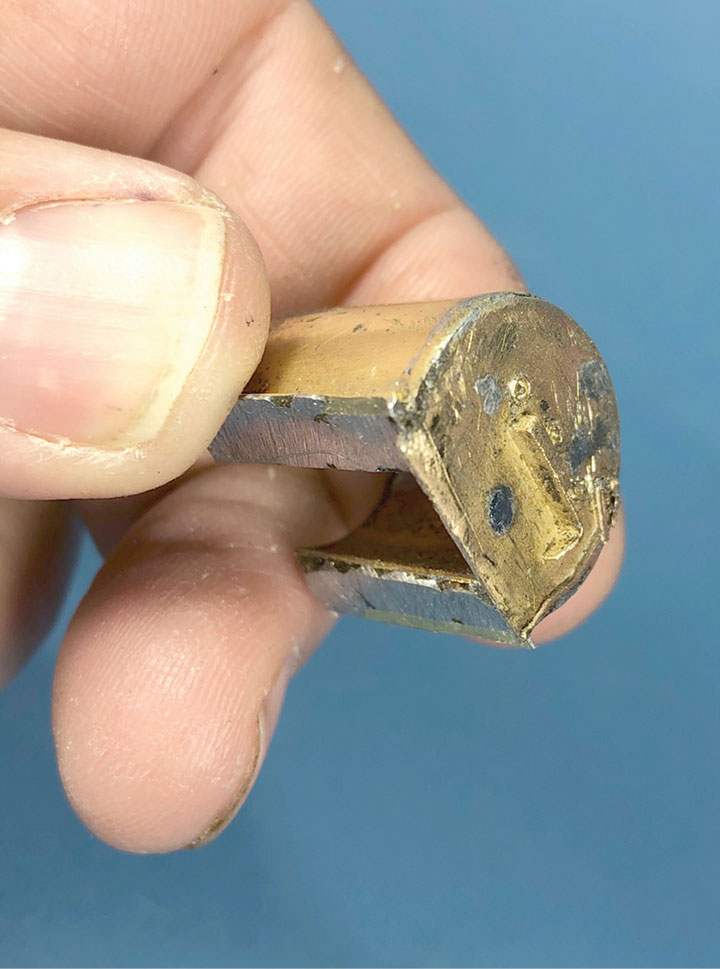
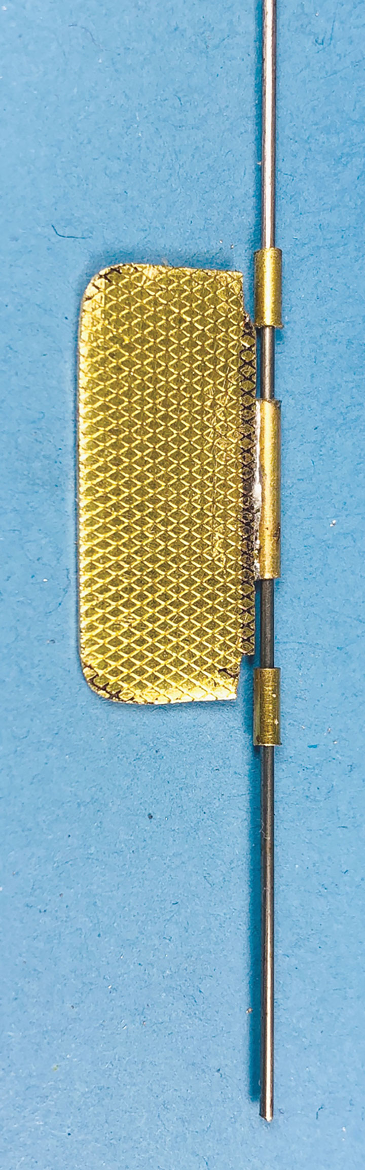
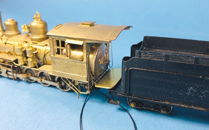
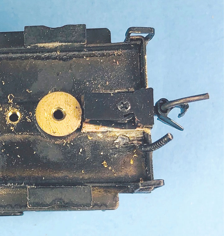
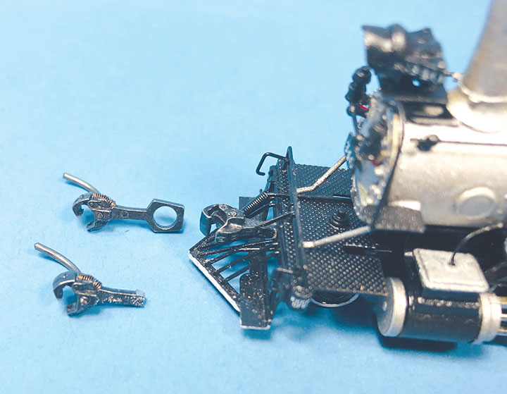
I find the easiest way to mount a motor is by creating a brass cradle that screws to the locomotive’s frame. With #340, I cut a section of 9/16-inch diameter K&S brass tubing to the same length as the motor. I cut two thirds of the diameter of the tubing away leaving the last third as a nice round cradle for the motor. Then I cut the same length of brass C-channel. This C-channel was soldered to the tubing cradle so that the whole assembly could be mounted to the locomotive frame. Before soldering the two pieces together, I filed the C-channel to the right height so the motor’s shaft would align nicely with the gearbox shaft. Using the existing motor mounting hole in the model’s frame, I drilled and tapped a hole in this new motor cradle to accept a 2mm screw. With the motor cradle screwed in place, a thin bed of silicon was applied and the motor mounted in place. Before the silicon set, I ran the motor with a power pack to help get everything in proper alignment. I then set the model aside for a day to let the silicon harden.This model came with a huge open frame motor in the cab, and Balboa Models didn’t make any attempt to create a detailed cab interior or include a back head. I could have just left the cab empty, but the new model was small enough that I had room to create a rudimentary cab interior. I used a piece of 5/8-inch K&S brass tube as the base. About 1/3 of the tube was cut away so that it would slip over the motor. Then I soldered a Precision Scale #32388 back head casting to one end of the tube. The back head wasn’t perfectly round, so I wrapped the tube with a sheet of .020-inch brass sheet while following the profile of the back head casting. I bent the excess brass to fill in the missing cab floor. All of this was soldered together, then filed to fit around the motor and inside the cab. The back head was made to overlap the back of the cab floor and the whole assembly fits flush with the front inside of the cab. The cab roof isn’t removable, so this cab interior slides over the motor from the back. Because of space limitations, there was no opportunity to add any more details, so I decided to keep the details simple and filled the predrilled holes in the back head casting with solder. There was a small void where the boiler wrapper went around the brass tube core, so I filled that with solder to add weight to the locomotive. I realize that this back head assembly is in no way accurate for this class of locomotive, but it sure looks a lot better than an empty space with an electric motor in the middle. Many older models don’t come with an apron on the back of the locomotive for the fireman to stand on. This is a really easy detail to add and dramatically improves the appearance of the model. I cut a piece of Precision Scale .025-inch diamond plate sheet to the shape of the apron. I used my calipers to measure the space between the locomotive and tender. I also made sure the apron would not bind when the locomotive went around curves. I then cut a piece of .060 OD brass tube that I soldered to the middle 50 percent of the apron. This will be used to form a hinge. I then cut two pieces of the same tubing to fill in remaining parts of the hinge. A piece of .032-inch diameter piano wire was then inserted through all three pieces of brass tube and cut slightly shorter than the total length of the tubes. I used steel piano wire, since solder won’t stick to it. With the assembly all together, I then soldered the two small pieces of tubing to the back of the locomotive cab. I determined its location by finding where it will line up sitting level on the front of the tender deck.A few pieces of metal and some time have dramatically improved the appearance of the cab on this model. It’s not prototypically correct, but is a great representation of what should be there. It certainly looks better than a gigantic hole with a motor sitting in it.The Balboa model came with a non-operating rear coupler casting that I removed. Unfortunately, I also had to remove a beautiful buffer casting since it couldn’t be modified to work with a Kadee #714 coupler. To mount the Kadee coupler to the tender, I soldered a piece of .032-inch-thick brass to the underside of the tender frame to create a base for the coupler box. The end beam on the tender was filed so that the coupler box would sit on the brass base and also be flush with the end beam. With the box in place, I marked where the mounting screw would go, and then drilled and tapped the coupler base for a 1.4mm screw. A 5mm-long 1.4mm screw was then used to mount the coupler in place.The model also came with a non-working front coupler casting. I removed this casting to make way for a working front coupler. With the front coupler casting removed, there was only a hole in the end beam. I like to use a Kadee #58 coupler with the loop and trip pin cut off to create a working front coupler on HOn3 locomotives. In order to mount the modified #58 coupler, I soldered a short length of .092-inch-square brass tubing to the under side of the locomotive pilot. This created a pocket for the shaft of the coupler to be glued into. Once in place, this coupler was checked against a coupler height gauge to make sure it was at the perfect height. Thin styrene shims were used around the coupler shaft to fine-tune its height.
I bought my Balboa model off eBay for $125.00. It was someone else’s project that was never completed and was in pieces. But from the photos, I could tell that all the important parts were there, and it would be a great candidate for this article. So, I hope to demonstrate an affordable way to acquire a nice HOn3 locomotive.
Before I start describing #340, let me explain what I look for when I select a model for a brass-bashing project:
1. Wheel wear. A little is OK, but it takes a lot of running to wear the plating off a set of drivers. If the plating is worn off, then it’s more likely the holes in the side rods and other things are worn too. I avoid these models. It’s not worth putting a lot of effort into a model only to find that hard to find parts, like side rods and valve gear, are worn out and will need to be replaced.
2. New old stock, versus slightly used. I do prefer a stock model that hasn’t been run or modified. It’s usually easier to upgrade. However, a model that shows a little wear tells you that it’s probably a good runner since it’s actually been run. I’ve seen many new old stock models that have all sorts of problems from the factory, which are hard to resolve, making them a less desirable candidate for upgrading than one that’s been run a little.
3. Painted or not. I’m not willing to pay more for a good paint job since I’ll probably be re-painting the model anyway. A painted model and unpainted model, both get grit blasted the same way before I paint them, so if I can get a poorly painted model for less money, I’ll go for it.
4. Drop damage. A big red flag for me is damage incurred to a model because it’s been dropped on the floor, and it’s extremely hard to fix a bent frame. It’s difficult to repair a bent cab roof or dented tender side. Generally, I will stay away from models that show signs of drop damage.
5. Unassembled models. These can be a gamble with big rewards. Lots of times people take their models apart to paint them and never get back to them. Since I will be disassembling the model anyway, it doesn’t make a lot of difference to me. What is important is that all the difficult to find pieces are there. I can replace missing screws and basic things like that, but drivers and valve gear are hard to find.
6. Non-running models. Most likely I’m going to re-motor the model anyway, so usually a non-running model is just fine by me. Over the years, I’ve bought some non-runners for very good prices only to find out that replacing the rubber coupling with 10 cents in tubing solved the problem. If it looks like something more serious like the valve gear is broken, or the gears are worn out, then I might pass on the model.
7. Importers. Most of the early 1970 and older models were made in Japan, while later models shifted to Korea. The early Korean models are hit and miss for quality. For brass bashing projects, I really like the Japanese models. They may lack details, but their quality is usually excellent. The Japanese mechanisms are generally straight, tough and well built, making them great candidates for upgrade. The missing details can easily be added, but fixing a poor mechanism can be almost impossible to solve.
Now that I’m done explaining my criteria for picking a model, I’m going to walk you step by step through the creation of my model of D&RGW #340. I’m going to go to the extreme with this model. Keep in mind that you don’t need to make your project as complicated as mine, and from my construction examples you can pick and choose the techniques that are important to you. Also, each model is different, so there is no “one size fits all” approach. I’m simply hoping that this project will inspire you to bring out your inner brass bashing skills and create your own desired model.
I’ve covered a lot in this article, and we are not even half way through this project. In the next issue of the Gazette, I will continue modifying this brass locomotive into a faithful reproduction of D&RGW #340.