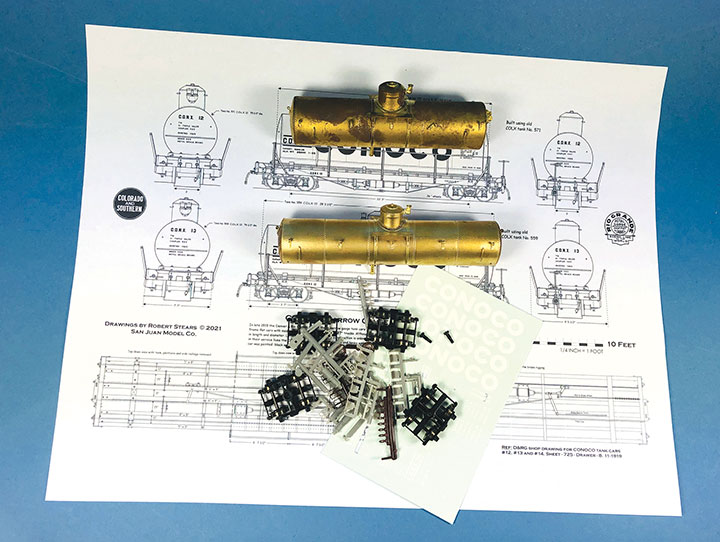
I’ve always been interested in the oddball equipment that the narrow gauge railways collected and I enjoy the challenge of trying to replicate these cars in miniature. When I saw Robert (Bob) Stears’ plans in the November/December 2020 GAZETTE for Conoco tank car number 14, I knew this was a prototype that I wanted to model. A few years before his passing, Jim Vail had given me a box of brass tank car bodies that Dick Truesdale of Westside Models had given him. Since then, I had been looking or a suitable project for these tanks, and here it was. With Bob Stears’ plan in hand, I compared the brass tanks to the drawing. Unfortunately, none were even close to the dimensions of CONX 14. I thought that the project was over until I noticed that the plan listed the tank sizes for CONX 12 and 13. All three cars shared the same frame, but the tanks were all different. In that box of tank bodies, I found a perfect match for number 13 and a very close match for number 12. My project was back on track! I switched directions and decided to build 12 and 13 and leave CONX 14 for another day.
I searched my book collection, and all the online sources that I knew of, but I could not find a single photo of CONX 12 or 13. I reached out to Dave Grandt, the expert on all narrow gauge tank cars. Dave was kind enough to share photos of similar cars with me, but he had never seen a photo of CONX 12 or 13 either. I then exchanged emails with Bob Stears. He had never seen photos of the cars either and had drawn his plans based on a D&RG shop drawing that he found in the Denver Public Library collection. Bob shared plans with me that he had made specifically for CONX 12 and 13, and were going to be in a future issue of the GAZETTE. Photos of the prototype would have been handy, but with such esteemed sources coming up empty, I simply moved forward with the best information that I had.
With drawings and photos in hand, I dug through my scrap box of parts to see if I had all of the other major components needed for this project. Luckily it turned out that I had plenty of Grandt Line detail parts, the correct trucks, decals and a mountain of styrene and brass material for the models. With that, I set out to create CONX 12 and 13 in miniature. I want to thank Dave Grandt and Bob Stears for their Title help.
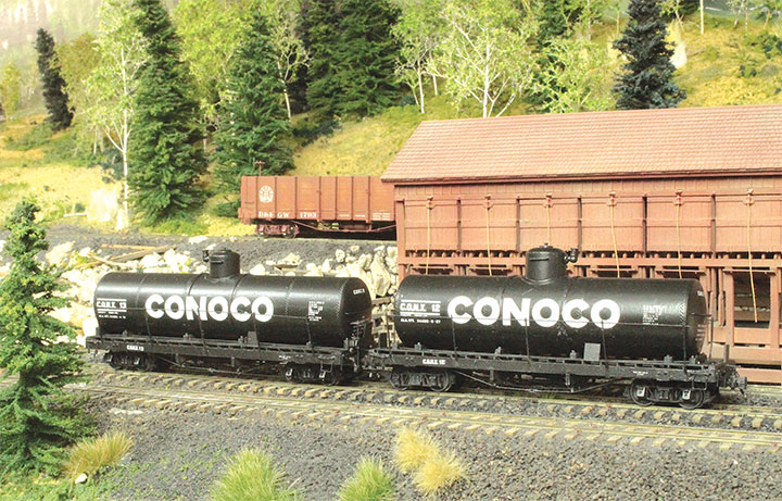
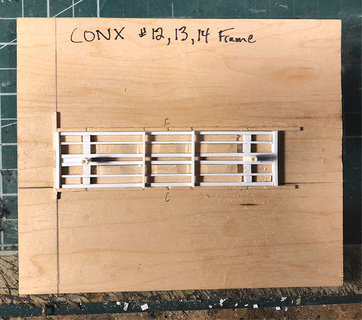
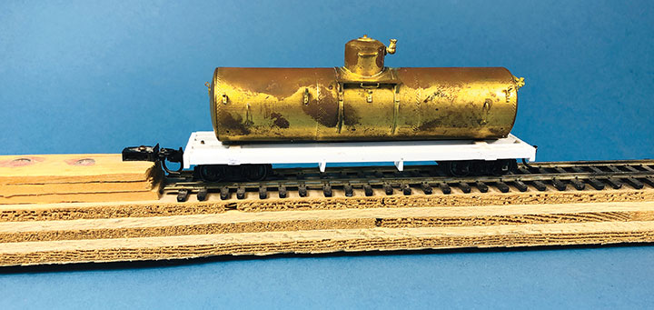
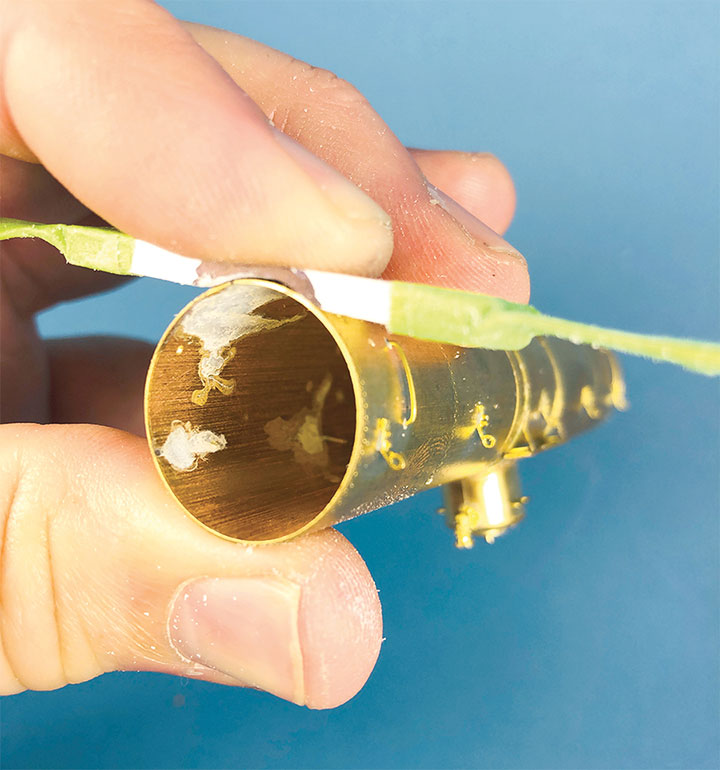
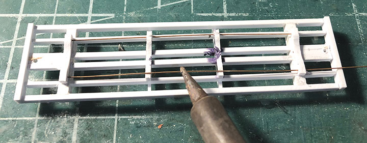
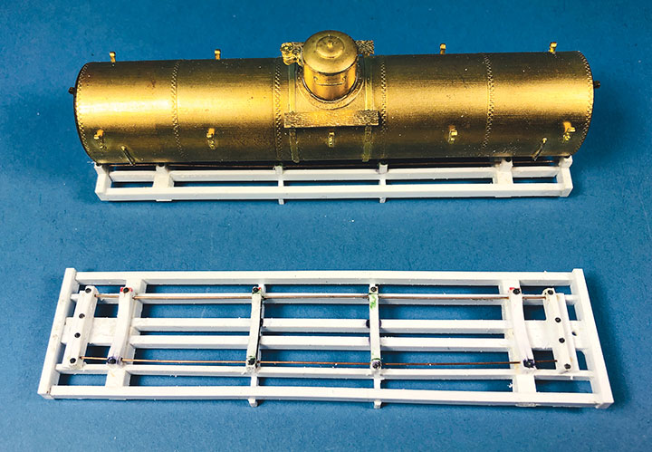
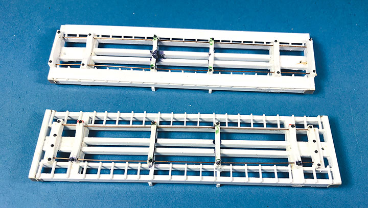
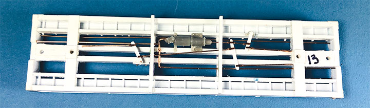
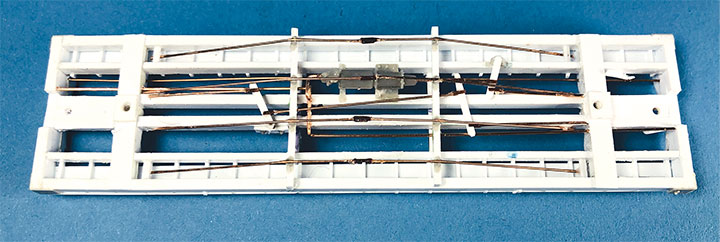
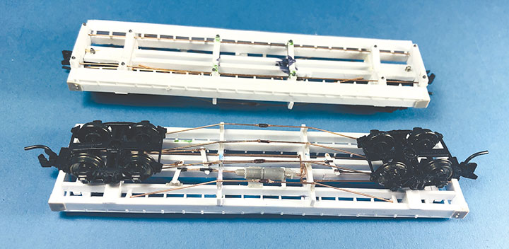
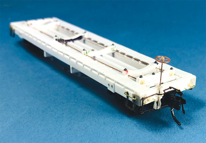
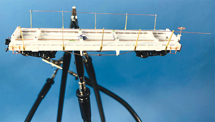
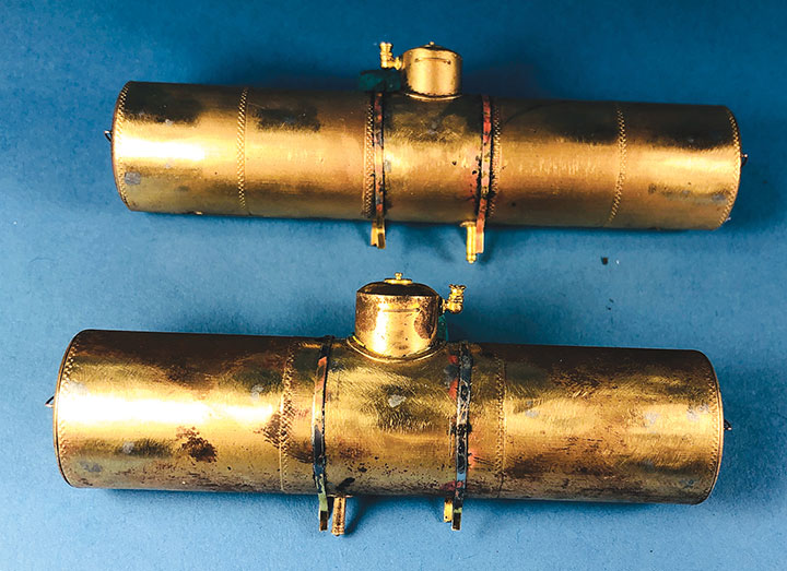
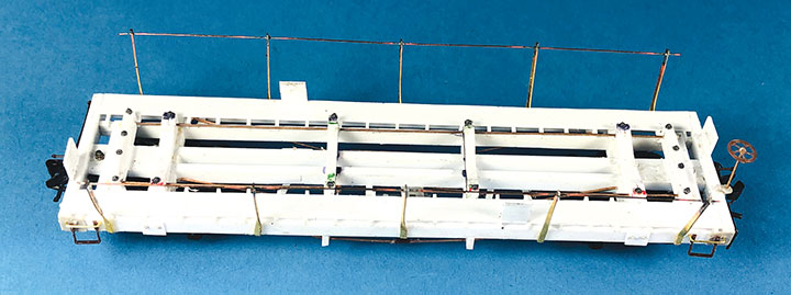
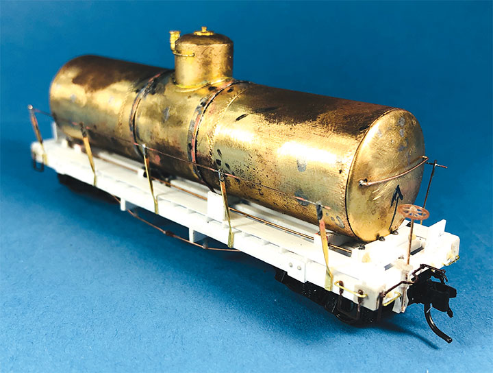
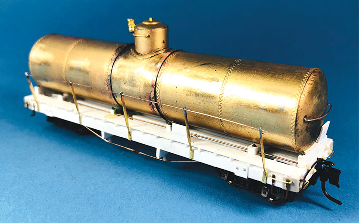
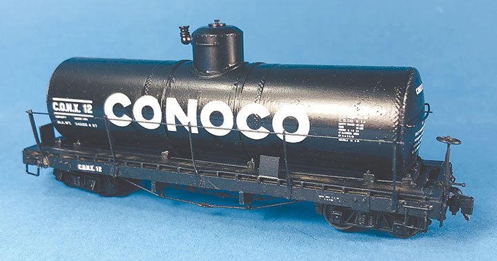
Conoco tank cars 12 and 13 have been set out on the author’s HOn3 layout at Vance Junction waiting for the local crew to bring them to the Conoco dealer in Telluride.With plans in hand, I dug through my parts to make tank car “kits” for CONX 12 and 13. I also used a variety of Evergreen styrene strips, wire and brass strips. If you want to assemble your own “kit,” the tank in the HOn3 Precision Scale Co. kits for the Frameless and Narrow Frame tank cars would be a suitable stand-in for CONX 12. The tank for CONX 13 is longer and skinnier than number 12, and I don’t know of a suitable substitute. It would probably have to be scratchbuilt or 3D printed.Since I was making more than one identical frame, making a jig helped with assembly and consistency. Since I still intend to make CONX 14 someday, I had a third reason to make this jig. The dimensional lumber in the prototype plan are odd ball sizes. Since a one-inch difference in HO scale is hard to see, I chose to use the next closest lumber sizes offered in Evergreen styrene. The end beams are 6- x14-inches, so I made my own by gluing 6- x 8- and 6- x 6-inch “timbers” on top of each other. The outside and center beams are 6- x 10-inches, and the intermediate beams are 4- x 10-inches. The truss rod beams are also 4- x 10-inch styrene. I used a .060-inch square block for the coupler box support and to set the distance in from the end beam where the bolster would be assembled. The screw hole for the truck is .125-inch OD styrene tube. The rest of the bolster is made up of .125-inch square blocks. Missing from the photo is the 1- x 12-inch cap that I put over the bolster blocks.I notched the end beams to accept Kadee #714 couplers and used Blackstone 3’ 7” D&RGW freight trucks with these models. With the larger elements together, I weighed both cars. They came in at around 1.5 oz. each, which is about perfect for an HOn3 car this size. I didn’t end up needing to add any additional weight in the tank. If you make your CONX 12 using the plastic Precision Scale Co. tank, don’t forget to add some weight to the car. The frame weighs nearly nothing.I find that the trickiest part of scratchbuilding rolling stock is getting the trucks to swivel freely, and have the coupler at the correct height. I ended up adding a 4- x 10-inch block on the bolster king pin to set the trucks farther from the frame which would allow them to swing freely, and to raise the coupler height. I checked the coupler height using my home-made gauge. NOTE: On the finished models, I shaved the coupler blocking down some more to get a better match for the coupler height. The next task was to build the frame and saddles for the tank to sit in, and on top of, the car frame. Each car has 4 saddles. To get them all curved the same, I cut 6- x 10- and 4- x 10-inch blocks oversized. I taped the blocks tightly together and used a curved file to match the contour of the tank. Once I was happy with the curve, using the tank as a guide, I glued the saddles in place on the frame.The tanks on the prototype cars had end blocks to keep them from sliding on top of the frame and from buffeting forces on the train. These end blocks were joined together with rods that run through the four saddles. The entire assembly worked together to form a cradle for the tank. Because of the imperfect nature of scratchbuilding, it wasn’t practical to pre-drill all the blocks before assembly. Undoubtedly, something would be out of alignment and the tension rod would have an un-prototypical bend in it. Drilling the center blocks once they were installed was also impossible. What I decided to do was drill holes in the end blocks and then using a soldering iron, I heated .015-inch phosphor bronze wire so that it melted its way through the styrene saddle blocks and into position. Once in place, I used Squadron putty to clean up the melt line left in the styrene. This worked surprisingly well.To finish the tank saddles, I added Grandt Line #5123 NBW castings to simulate the bolts on the ends of the tensioning rods. Using the drawings as a guide, I added Grandt Line #5096 NBW castings where the tank car saddles would be bolted to the flat car frame.It was now time to install the walkways down the sides of the cars. Using the drawings, I installed a lot of 2- x 4-inch blocks on edge between the outer and intermediate stringers. On top of those blocks I added a parallel set of 1- x 8-inch boards for the length of the car. The photo shows one car with just the blocks in place, and the other car with the boards installed over the blocking. Notice that the longer tank on CONX 13 (top) requires the tank saddle to be the full length of the car, while CONX 12’s saddle (bottom) is shorter and inset from the car ends.I realize that few people ever see the brake details on an HOn3 model, but I just don’t feel right leaving them off. So, I scratchbuilt all of the brake rigging on the cars following the drawings. The first thing I did was bend and install .020-inch phosphor bronze wire for the main airline that runs the length of the car. I temporarily removed one of the truss rod beams to make this easier to do. Then I installed a brake cylinder from a Grandt Line #5040 Westinghouse NG Brake Set. More .020-inch wire was used to “plumb” the cylinder into the main airline. Number 70 holes were drilled in the truss rod beams to allow the brake rods to pass through them. I made the brake rods from .015-inch diameter wire. The clevises on the ends of the rods were made from Grandt Line #5039 turnbuckle castings with one end cut off. The brake levers are 1- x 4-inch styrene with the corners chamfered off. Where the rods would connect to the trucks on the real car, I simply glued the rod ends to the car’s center beam to keep them out of the way of the truck swing.Most HOn3 models use fishing line threaded through turnbuckle castings to simulate truss rods. Since this car has an open deck, the ends of the fishing line would be hard to disguise and look terrible. I decided that I’d have to use .015-inch-diameter wire instead of fishing line. Since I was going to use wire, I thought it would be a good idea to install the wire on the Grandt Line #5039 turnbuckles in such a way that the hole in the turnbuckle would remain open, and I could install a piece of strip wood through the hole like the prototype does to keep them from working loose. I managed to accomplish this, but it was a lot of work and very difficult. If I were to do this again, I’d just run a single piece of wire through the turnbuckle and forget about keeping the hole open. It would have been a lot easier and make for a stronger joint. In the end, I couldn’t get the wood through the turnbuckles anyways. I used Grandt Line #5051 5-inch queen posts.With the underbody details complete, I reinstalled the couplers and trucks to help protect all those delicate details that I painstakingly installed under the frame. It was now time to focus on detailing the side and top of the car frame.I wanted to dress up the frame by simulating as many of the details that the prototype had. I added 1- x 12-inch styrene with Grandt Line #5045 NBW castings to simulate the ends of the bolsters. The corner braces included in the Grandt Line #5231-8V Victor Miller casting set were close enough to match CONX 12 and 13. I added Grandt Line #5123 NBW castings on the frame ends to simulate the ends of the truss rods. Grandt Line #5130 stirrups were used on all corners. Using a grab iron folding jig from a Grandt Line boxcar kit, I made grab irons for all four corners. The side grab irons are longer than the end ones. Precision Scale air hoses were also added as well as Grandt Line #5185 uncoupling levers. The brake wheel and its assembly are from the Grandt Line #5040 set I used for the brake cylinder. This completed the detailing of the frame.When I started this project, I thought that the railings were going to be the hardest part to make. In fact, the brake rods and truss rods were much more difficult, and the railings turned out to be fairly easy. The stanchions are made from Simpson Models #332-HO .010- x .034-inch brass strip stock. I drilled a #78 hole in one end, then twisted the other end 90 degrees and added a slight bend to simulate where the railing leans outward from the tank frame. To install the stanchions, I glued the end stanchions in place. Then I threaded the remaining three stanchions on a piece of .010-inch diameter wire and put the wire in place between the end stanchions. I left the wire extra-long so that I could move the stanchions around without everything falling apart. I then glued the center stanchion in place and split the gap for the remaining two stanchions. Once the glue was dry, I soldered the rod to the tops of the stanchions. This made a very strong assembly. I then clipped the .010 wire to length. NOTE: The photo makes the rods and stanchions look crooked. That’s just a weird optical affect from the digital camera. They are as straight as I could possibly get them.These tanks we intended for some unknown model that Westside Models had released. Because of that, they had all sorts of details that needed to be removed. I used my resistance soldering iron to remove them. With the details removed, I had lots of holes and old solder to contend with. I find that the easiest way to fill holes in brass is to flux the hole and fill the hole with solder. I try to leave a raised button of solder over the hole. I then file that button smooth to the surface of the tank. This leaves scratch marks from the file that will show through the paint, so I follow that up with a medium and fine grit Cratex blocks. This brings the surface back to a polish where the solder plug will never be seen. I use this method when I’m brass bashing locomotives too. With the tanks cleared of the old details, I set about adding new ones. This task was simply to add .020-inch-diameter wire handrails on the tank ends, and new straps for holding the tank to the car frame. I made these straps from Simpson Models #970-HO 10- x .046-inch brass strap. The brass straps were cut so that their ends fit into the frame. I didn’t bother trying to detail their connecting hardware since it will never be seen, and I wanted to paint the tanks separate from the frame.Here is what the finished tank car frame looked like prior to painting. You can see that I also added stacked 2- x 8-inch styrene for the hazardous cargo placards.The assembly of CONX 12 is complete and the car is ready to go to the paint shop.This is how CONX 13 looked after it was fully assembled and waiting to go to the paint shop.I painted the tanks and frames separately. I painted the tank like I would paint a brass locomotive. The bodies were grit blasted, painted with Scalecoat I Black paint and baked in my brass cooker. I painted the frames using several light coats of gray and brown Humbrol paint. I used a PBL scratch tool to scratch the walkways between coats to simulate weathered wood. With the “wood” complete, I gave the top surfaces a spray of Floquil Black, and brush painted the metal underbody details with the same black paint. This resulted in a weathered wood look on the underside and a weathered black paint on the top. The frames were then over-sprayed with a flat clear coat, and the tanks with a semi-gloss. I tried to create a slightly weathered look that represented the material types. Wood would weather quicker than the metal tanks. The decals are from a ThinFilm HOn30 CONOCO set.