Introduction
When I set out to build my HOn3 White Pass and Yukon layout, I wanted everything on the layout to be DCC controlled, and I wanted to use Tortoise switch machines throughout. Another goal was to incorporate as much track detail as I could. Tinkering with a Tortoise switch machine one day gave me the idea that I should animate all of the switch or turnout targets on the layout. It would be an interesting detail, but also increase the realism of the layout’s operation.
Since all my turnouts have Tortoise machines, I only needed to design one method of linkage to operate the targets. I used a few different styles of switch stands and targets, but fundamentally they all operate the same way. Simplicity, smooth operation, and reliability were the objectives of the project.
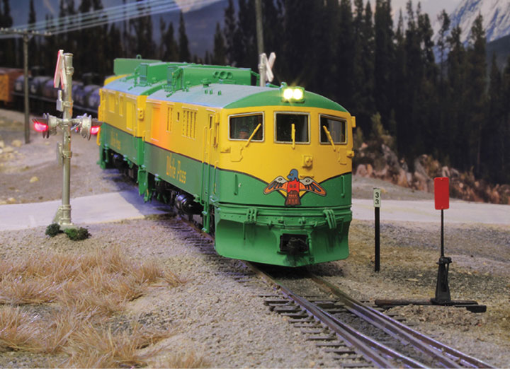
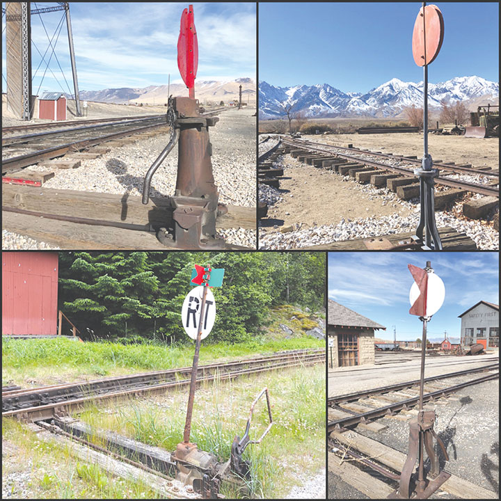
Prototype hand throw switch stands come in many shapes and styles, but they all serve the same purpose to line a turnout to the normal or diverging route. While the switch points are the final indication of the position of a switch, the target serves to indicate the turnout’s position at a much greater visual distance. Different railroads used different switch target designs, but ultimately, they all work the same. When a turnout is lined, the target will turn ninety degrees. Various shape or color targets are mounted to the mast, and when it turns, different targets are visible to a crew. The aspect, or visual shape and color of the target, which is perpendicular to the tracks, is the indication of the turnout’s position. On many turnouts, no target perpendicular to the tracks indicates that a switch is lined normal. This is what I modeled as it is consistent with the White Pass & Yukon.
Parts and Plan Overview
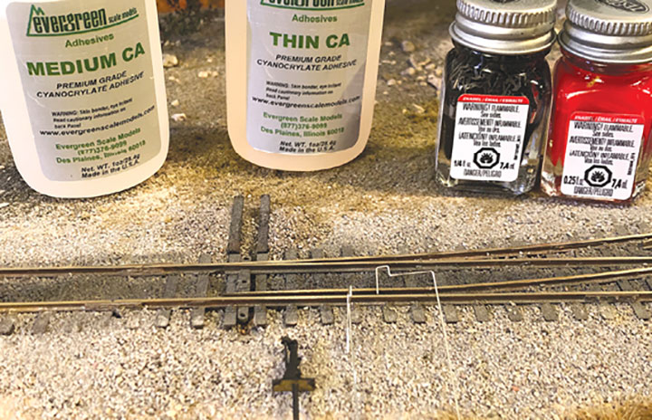
I began with the pieces that would start as off the shelf parts. Since my layout isn’t too large it made sense to build all of the operating target switch stands at the same time, like a little assembly line operation. The Tortoise machines would be the basis of the mechanical operation to carry the motion up to the target. I used a few styles of switch stands, the majority being Overland Models #9815. These stands are what really gave me the idea of animating the targets since they are ultimately designed to do so already. The problem with them is that they leave most of the mechanics up to you to figure out, but more on that later. I also used some Details West #SS-914 and #SS-915 switch stands to add variety. While railroads often standardized parts, there are always a few odd ball things around. To me this is artistic license, rather than finding a photo of each specific switch stand for every location.
Building the Components
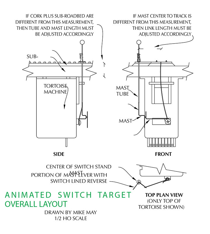
The first step was to design the parts in AutoCAD, so that I could figure out the correct lengths of everything. The drawings that I made are a part of this article so for anyone wanting to build these parts, it’s a step that can now be skipped. With the design work done, the next step was to fabricate the parts.
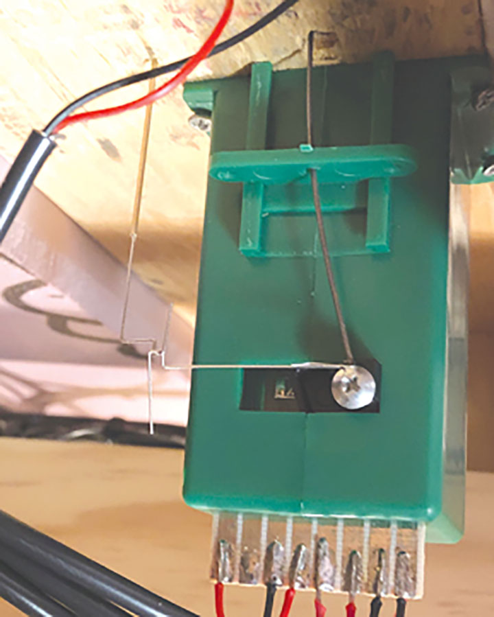
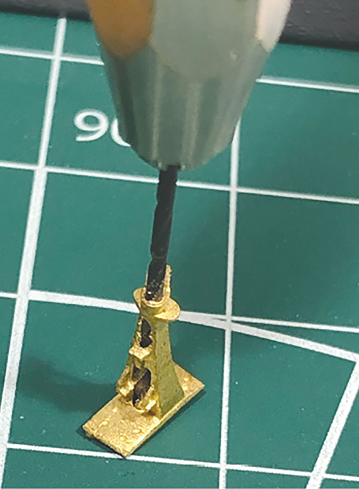
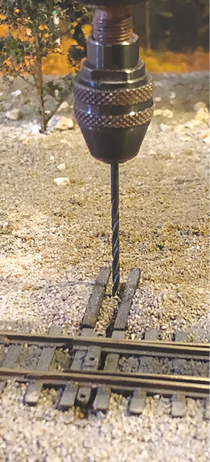
The general idea of operation is for a brass tube to be passed through the switch stand and down below the sub-roadbed of the layout. The mast on which the target is mounted, passes through the tube and below the layout where it is bent into a lever. The lever is moved 90 degrees by a link from it to the Tortoise machine. The Overland switch stands that I used primarily on the layout are already intended for animation and are drilled for the brass tube. It did need a little enlargement so I could use the same brass tube as on the other stands, rather than the tube provided by Overland. On the other switch stand castings, I filed a small flat spot centered on top of the casting, then using a #67 bit, I carefully drilled down, and through the top of the switch stand as well as through the base. Next, I cut a piece of K&S Engineering #815035 brass tube according to the drawing, working out to the height of the switch stand, plus the total depth of my sub-roadbed, plus a bit more to extend below the top of the Tortoise machine. The tube gets installed in the stand and glued in place with thin CA, then I gave the whole thing a quick coat of black paint.
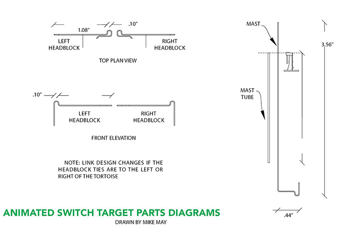
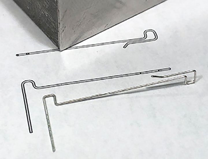
The target mast is made from .015-inch music wire from K&S Engineering. Most of the mast is hidden inside the tube or below the layout, but it does make up the visible moving portion of the mast. I cut a section of wire about 6-inches long which is overly long to start with, then filed one end of it clean to be the visible top end. I marked the mast with a sharpie where the top of the switch stand would be so that I’d know in the next step where the collar is to be placed. The length of the hidden portion of the mast needs to be 213/16-inches before the first bend according to the drawing. This distance should be changed for other layouts based on the thickness of sub-roadbed to the tie height. At the correct spot, according to the drawing, I made a 90 degree bend. Then following the drawing exactly, I made the rest of the bends for the lever and its hook.
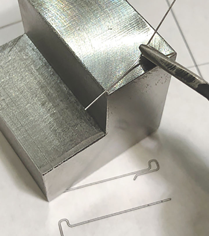
The link is easy to bend into shape following a printed copy of the drawing. I used a pair of small needle nose pliers to hold the music wire, and then bent it against a piece of metal for a solid surface. I have a piece of steel that a friend machined to a 11/2-inch cube with a ¾-inch notch cut out, and it works wonderfully as a miniature anvil for this kind of work. The size of the hooks on each end are important so that it both connects to the mast lever as well as snaps onto the throw rod correctly. The overall length of the link is also very important and determines the two positions of the target when the switch is lined. This length is relative to the distance from the switch’s centerline to the switch stand’s centerline. If that distance is lengthened or shortened from the drawings, then the link length should be changed by the same amount.
Tortoise Machine and Switch Stand Installation
The track on my layout is all HOn3 code 70 Micro Engineering glued to N scale cork roadbed with silicone adhesive. The cork is laid on ½-inch plywood as a sub roadbed. Before setting turnouts, I drill a ¼-inch hole through the cork and plywood directly below the center of the switch points. For smoothly operating targets it’s important that the switch operates correctly and without hesitations.
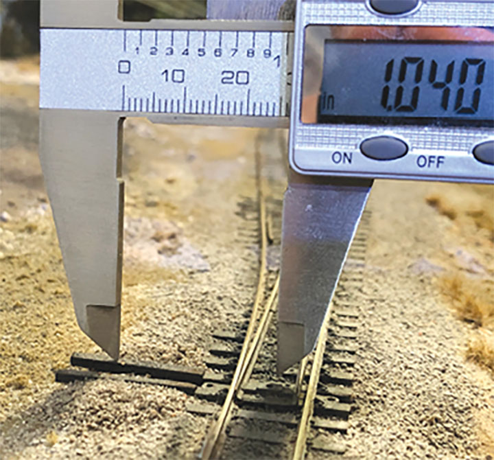
It’s important that the switch stands are installed the correct distance from the track centerline, so the linkage turns the mast 90 degrees. This distance can be changed, but the link needs to be changed proportionally in that case. For my layout, I used a distance of 1.04-inch from track centerline to mast centerline. I marked this distance between the headblock ties and drilled through the roadbed with a 1/16-inch bit. The assembled switch stand with its tube gets installed and glued in place with medium CA. I make sure that the switch stand is glued solidly, usually using ample CA on the underside and later hiding it with ballast.
Collar and Link
Because the mast has a bend below the layout, it needs to be installed from the bottom of the tube then secured on the top. To accomplish this, I inserted the mast from below and ran it up as high as it can go, then used a small piece of painter’s tape to hold it in place on the top. At the marked spot on the mast where the top of the switch stand would end up, I made a collar to hold it from dropping back down. I wrapped a piece of .004-inch magnet wire a single turn around the mast and pulled it tight. A very small carefully applied dab of medium CA is all it takes to hold the wire in place. Do not run any CA into the tube seizing the whole thing up. When the glue sets, I trimmed the wire at the mast leaving a collar around it. The whole visible part of the stand gets painted black at this point. Then when dry, the masking tape is removed so the mast drops down into place.
The link is an easy installation making the assumption that access under the layout’s benchwork is good. The link is installed by snapping it onto the Tortoise throw rod first, so it stays in place. Then using tweezers and a steady hand, place the other end of the link onto the mast lever. It’s a simple gravity connection, but sometimes takes a little turn of the mast for the two hooks to fall into place.
Targets Installation
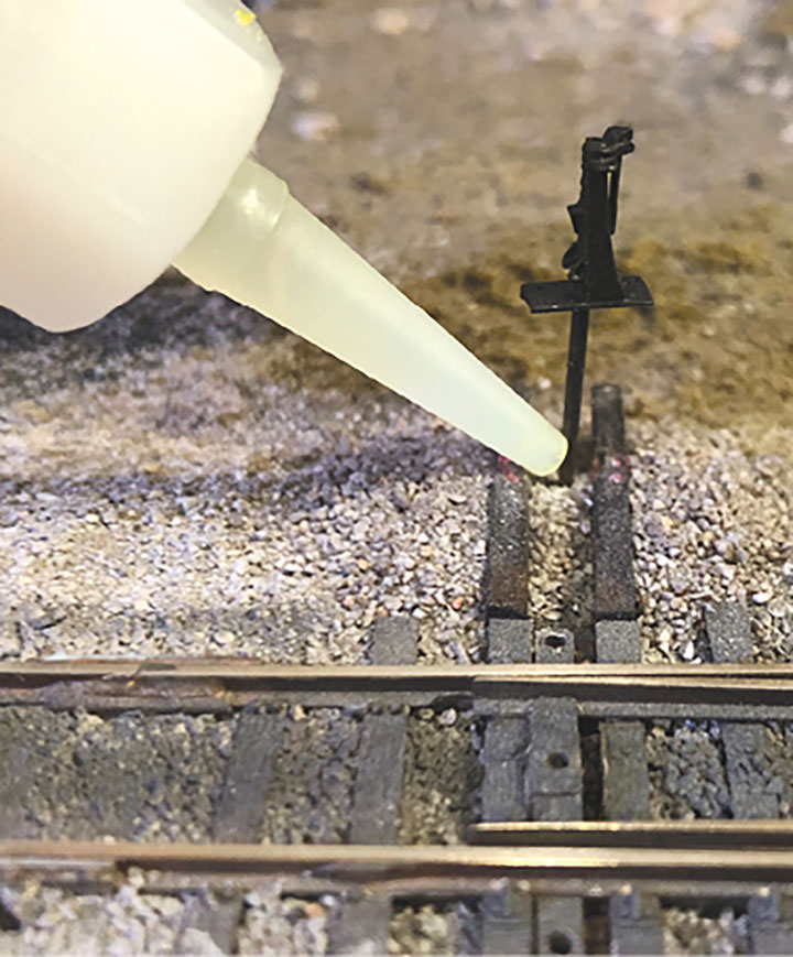
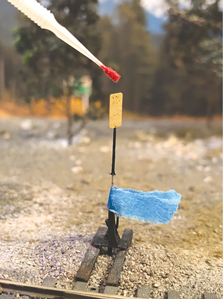
For my layout, I decided to use mostly red circular or rectangular targets to show a turnout lined for a diverging route. There are a few turnouts off of the main track where I used some different styles to give a little variety. Many railroads, the White Pass included, ended up sporting a variety of styles over the years. The Details West #SS-914 High Stands come with a great set of etched brass targets which is what I chose to use. I cut the targets from the sprue and carefully filed away any remaining flash. Before gluing the target, I lined the switch reverse, the mast turning accordingly so the target will be affixed perpendicular to the track. There are embossed rivet details on the etchings which should line up with the mast. Using a toothpick, I dabbed a minute drop of medium CA on the center of the target, then holding the target with tweezers, carefully placed it on the mast. It weighs almost nothing so the CA grabs very quickly. Once that was set for a few minutes, I applied thin CA to the whole joint. Allowing the target to set completely first. The last step was to brush paint the targets red on both the front and the back. I used Testors enamel paint, but really anything should do here.
Moment of Truth
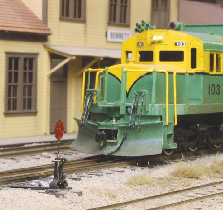
With everything assembled, it’s now the moment of truth. The turnout is lined reverse still with the target perpendicular to the tracks, and when the Tortoise is lined back to normal, the target should rotate 90 degrees so it is parallel with the tracks, showing the approaching train that they will take the normal route. I lined the turnout normal and was glad to find that my math worked out correctly, and the mast rotated nearly a perfect 90 degrees. One nice thing to keep in mind here is that on a prototype switch stand, it’s certainly common enough for a target to be a little out of line from true perpendicular, and parallel to the main track. Even if a switch stand doesn’t come out perfectly, that actually adds a bit to the realism. Adding this detail has been a fun little project to bring my layout to life in an unusual way, adding a bit of interest as well as functionality to the layout. Just as engineers on the railroad can feel confident in a switch position from the target, operators on my layout can feel the same confidence.