The unusual lattice construction of the Romley, Colorado, turntable has fascinated me since the first time I saw a photo on page 303 in The Mineral Belt Vol. 2, by David Digerness. So, I decided I wanted to build a model of this unique structure and made a drawing using the photo as a guide.
The only dimension I had was that the turntable was 50-feet long, everything else was guesswork.
I constructed a pit by cutting a 50-foot circle in ¾-inch-thick plywood and installed it on my layout. I found some 5/16-inch diameter oil filled bronze bearings and located one in the center of the pit. I roughed in plaster around the pit and then lost interest in the whole project. I’m not sure why this happened, but I don’t do well with angles, and I guess the thought of all those angles in the lattice made me lose interest. The pit is 69-inches above the floor, and I need to stand on a ladder to work on it, so out of sight, out of mind.
I did the bridge drawing in 1999, and not wanting to rush into anything, I finally built the bridge in 2021.
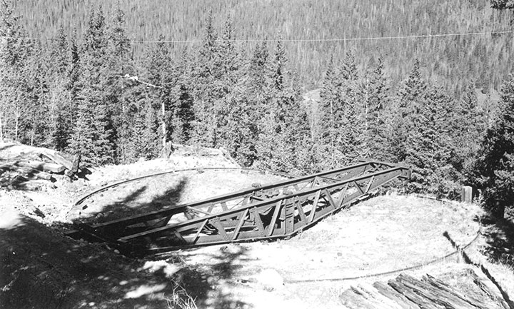
-Collection of Tom Klinger.
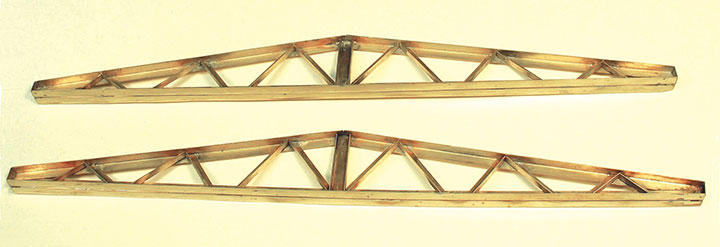
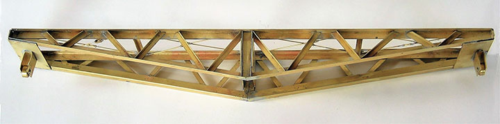
I have a good supply of K & S brass angle, and after trying various sizes, decided that 3/16 x 3/16-inch looked right and would be sturdy enough for the bridge. The 12-inch length of the K & S angle was perfect for a scale 50-foot-long turntable, with no splice necessary on the top girder.
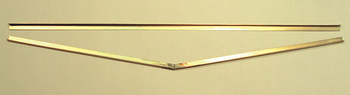
The most difficult part of constructing the side frames was soldering the angled butt joint on the bottom girders. When those were finished, I soldered the bottom girder to the top girder, soldering small end caps at each end. I started the interior bracing with the vertical center brace, then worked out from that with the angle braces. Each separate piece was a different length and angle, so any sort of mass production wasn’t possible. I placed the side frame over the drawing and used it to position each brass angle piece as I cut it to fit. I cut the pieces with a small shear, which distorted the brass. I snipped each flat side of the angle, which left a small center strip which I removed by bending the angle back and forth until it broke. I left extra length so I could straighten the brass with a jewelers’ flat nose pliers, then grind it to exact length on a disc sander. This was a cut-and-fit process and so tedious I only did a few each work session. It didn’t help that the grinding instantly heated the brass, burning my fingers.
Soldering the angle braces in place was easy because I used solder paste for everything. I used a toothpick to place a small amount of solder on each end of the angle and quickly soldered it in position.
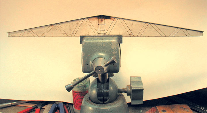
When both sides were complete, I soldered another full-length angle on the back of each top girder. This strengthened it and gave the appearance of a full, T-shaped girder.
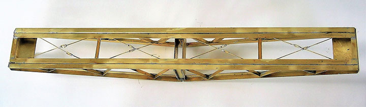
The next step was to assemble the sides into the bridge unit. I soldered angles and brass strips across the ends as spacers, being careful to make sure everything was level and straight. When I was satisfied with the fit, I soldered strips on each side of the center braces. The center post would later be soldered between these two cross pieces.
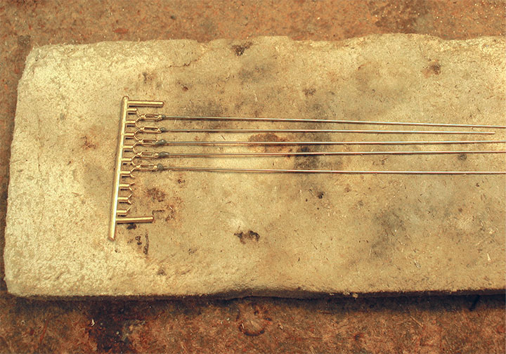
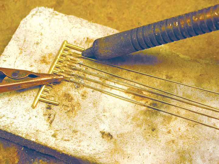
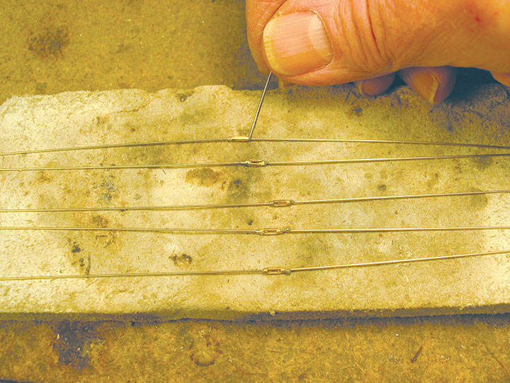
I was surprised by how few cross braces there were, but the Jack Thode photo from Tom Klinger clearly shows truss rods with turnbuckles between the sections. I made these the same way I make truss rods for all my freight and passenger cars, by soldering wire into turnbuckle castings. I use a miniature version of a production line process by leaving the castings on the sprue, as shown in the photos. After soldering the wire into one end, I clipped the turnbuckle from the sprue and did the other end. I like having open turnbuckles and this is an easy way to get them. I use long pieces of wire and cut them to length as needed.
The next step before locating the center pivot was fabricating the support wheels which ride on the ring rail. I turned the wheels from brass rod and used smaller rod for the axles. I bent .016-inch brass sheet to hold the wheels and soldered these on the ends of the bridge. Even though these actually work, they are just cosmetic, as I’ll explain in Part 2.
In the next issue, I’ll discuss finishing the bridge and installing it in the pit.