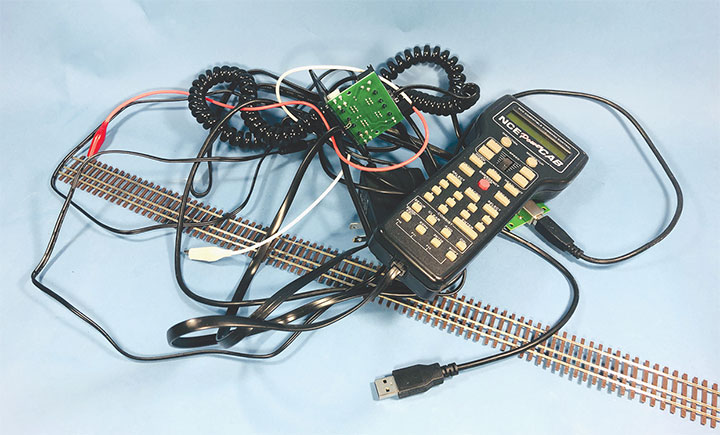
One of the aspects of this hobby that I really enjoy is the challenge of reworking brass locomotives. However, after rebuilding the drivetrains and adding DCC, I’ve never had a very good way of test running these locomotives. The best I’ve been able to come up with is a jumble of wires and a length of flex track that I temporarily set up on my workbench or coffee table. For the longest time, I’ve wanted to build a proper test track.After years of struggling with this less than adequate setup, I developed a list of criteria that any future test track would need to meet:
1.When I’m rebuilding a brass locomotive, one of the first steps I take is to make sure that the drivetrain runs smoothly. Often, I’ll upgrade the motor and sometimes I’ll replace the gearbox. Once this is done, I will use a DC power pack to ensure that the mechanism is running smoothly. My new test track was going to have to support DC operation.
2.When there is a bind in the mechanism or I’m trying to find a short, I will place the locomotive in a foam cradle upside down with test leads clipped to the model. Using another test lead, I will probe possible problem areas to find shorts. My new setup was going to need the ability to support test leads.
3.Once the locomotive that I’m working on runs well under DC power, I’ll install a DCC Decoder. I then re-test the locomotive performance to ensure the DCC Decoder and locomotive are working at peak performance. Having the ability to run the model under DCC power was going to be a must for this new test track.
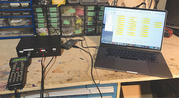
4.I use a dedicated NCE Power Cab, NCE USB interface, JMRI and my computer to program Decoders. The new test track was going to need to support these devices without having a jumble of wires all over my workbench.
5.Test running on a three-foot length of flextrack never seems to be long enough, but there isn’t enough room on my workbench for anything longer. The new test track was going to have to be at least two lengths of flextrack long and not clutter my workbench. Preferably, it would also have a curve in it to test for shorts as the wheelsets slide from one side to another.
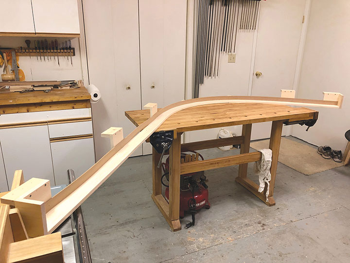
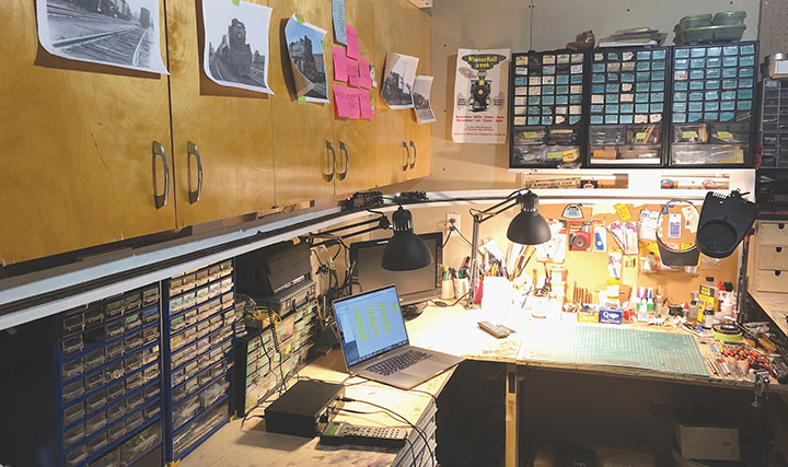
I wasn’t sure how I was going to meet these objectives until I saw a Facebook posting from a fellow modeler. He built a test track on legs that floated above his workbench like a skinny table. With this setup, he still had much of his workbench free for working on engines. This gave me an idea. Above my workbench are cupboards. I realized that I could take this raised test track idea and flip it upside down. My new test track would hang under the cupboards!
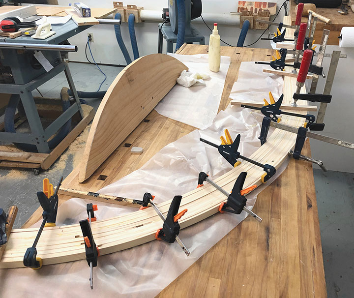
I wanted my test track to be pleasing and strong, so I decided to build it out of pine. The roadbed was made from laminated strips of pine like the roadbed I created for my Telluride branch (May/June 2014 Gazette). I made pine blocks for hanging the roadbed from the cupboards. Along the back of the test track, I added strips of Masonite so that a derailed locomotive couldn’t fall off the back and come crashing down on my workbench.
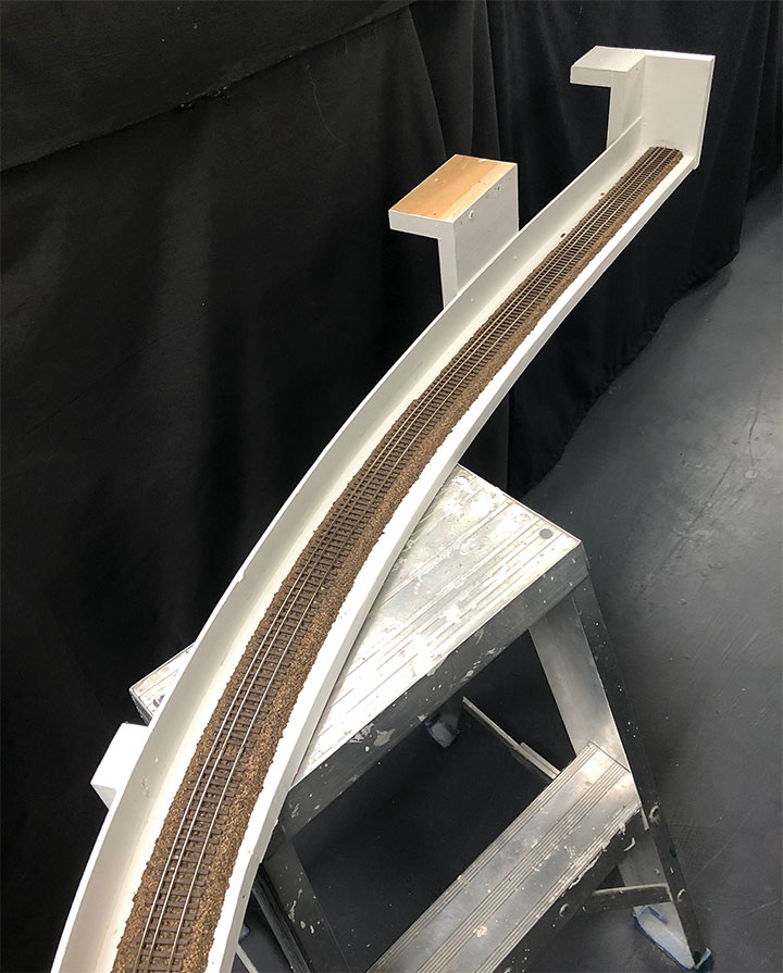
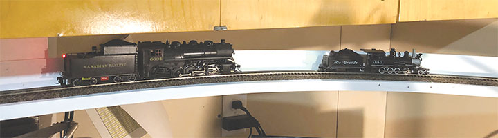
I test fit my test track in place prior to painting. Once I was satisfied with the fit, I painted everything with white paint. As much as I write about HOn3 modeling, I also have a sizable collection of Canadian Prototype steam engines that I enjoy working on. Because of that, I installed HO cork and HO/HOn3 Micro Engineering flextrack on my test track. This would allow me to enjoy both facets of the hobby.
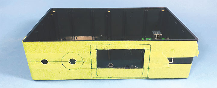
To solve the “jumble of wires” issue, and the fact that some of the NCE components were simply electronic boards that need electrical short pro-tection, I designed a junction box to house the components and provide simple plugs for connecting the wires. Through this box, I would plug in the NCE throttle and DC power pack. The box would also have outputs for the test track and test leads to clip to a locomotive. Following an internet tip from Phil Floyd, I also added a Decoder who’s grey and orange motor wires could be set as an output to run a non-DCC equipped (DC) locomotive using the NCE DCC controller. After sketching a wiring diagram, I ordered all the non-DCC components from Digi-Key.
Please follow along with the accom-panying photos as I walk you through this project and provide more details. In the end, my junction box is slick and met all my requirements. The test track is unobtrusive and works well. The whole setup far exceeded my expectations and I’m really pleased with the results. It’s made working on, and programing locomotives a lot easier. I hope my experience inspires you to create your own test track.
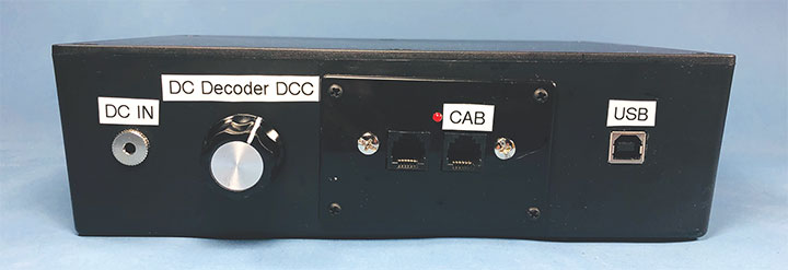
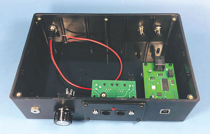
From left to right:
There is a 3.5mm input to plug in a basic DC power supply.
The rotary switch selects the three output options. The first option is power from the DC power pack input. The center option is motor power from the TCS T1. Finally, there is a straight DCC track power option.
The NCE faceplate is next. The NCE Power Cab needs to be plugged into the right plug for the system to work. The red LED will be on to indicate there are no shorts and the DCC Power Cab is working properly.
The USB port is for plugging in the cable supplied with the NCE USB board into my computer. This is used to program locomotives with JMRI Decoder Pro.
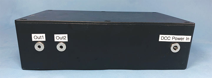
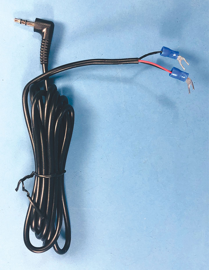
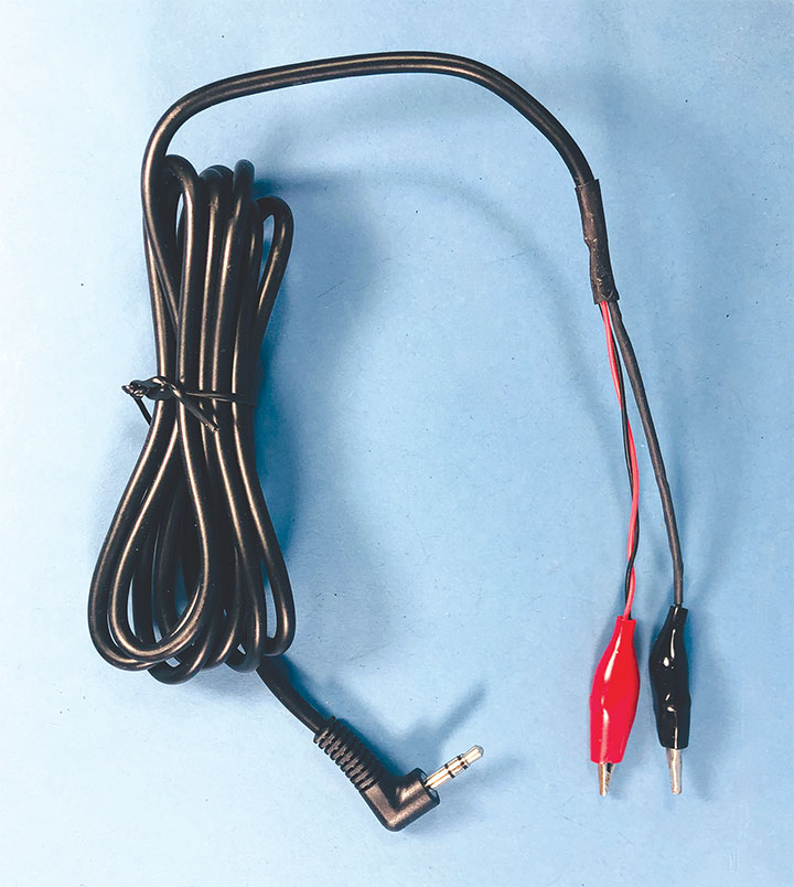
On the left, there are two identical 3.5mm outputs. One output will go to my test track, while the other can be used to plug in a second set of test leads for working on locomotives in a foam cradle.
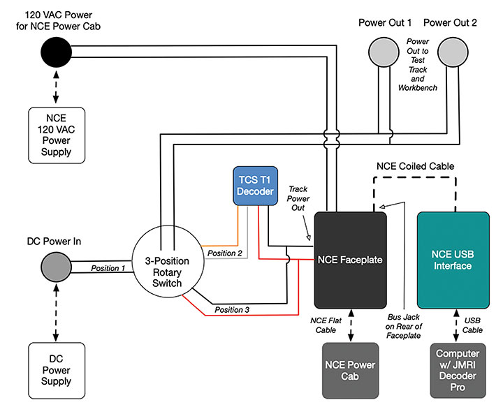
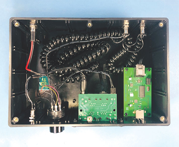
In the center/left is a TCS T1 Decoder. The black and red wires are connected to the track power outputs of the NCE faceplate. The orange and gray wires are connected as one input on the rotary switch. I programmed the Decoder to address “3333” since I’d never have a loco of that number, and then locked the Decoder from being accidentally reprogrammed. Selecting loco 3333 on the NCE throttle allows me to run a DC locomotive on the test track using the DCC throttle. I chose the TCS T1 Decoder because it has a high amperage output (1.3A) and should be fine with any HO or HOn3 DC locomotive, including those with open frame motors. This setup has worked so well, that I may never need to use a DC power pack with my test track.
Looking from left to right across the front of the box (bottom of photo): There is a female plug used for a DC input from a DC power supply. This is wired directly to the rotary switch beside it. The rotary switch is used to control the power to the two output sockets. The options are DC power, DCC Decoder power or straight DCC track power. Next, the NCE faceplate takes its power from the power adapter input from the back of the box, and sends a DCC signal to the Decoder and straight to the rotary switch. The last component is the NCE USB adaptor board. The USB board’s supplied coiled wire is stuffed in the box and plugged into the back of the NCE faceplate.
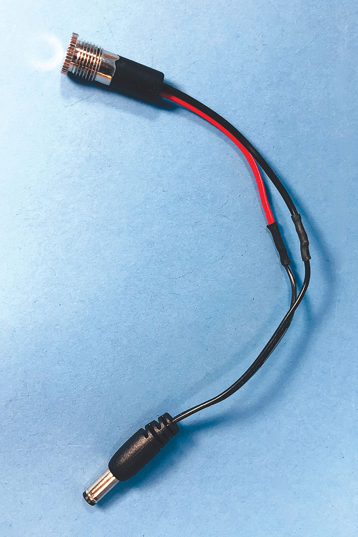
If you are in a larger scale, you will want to pick a different wire standard with larger gauge wire to handle higher current draws. This small wire has sufficient capacity for HO scale or smaller.