This project started several years ago while visiting an old friend, Don Dass. Don is an extremely accomplished modeler who once ran a business working on brass models for others. After working on many models, including a sizeable fleet of customized Sn3 Colorado & Southern models of his own, his interests had moved to ship building. However, Don had one last project that he wanted completed. He had collected an Sn3 C&S Overland model and a pile of parts as the starting point for creating C&S #58. He wanted this model to match a photo of the locomotive in 1915. During that visit, Don asked me to finish that project for him. Over the years we had collaborated on other projects and helped each other many times, so I was happy to take on this project for Don. What I didn’t know at the time was that this would be the most challenging project I’d ever attempted.
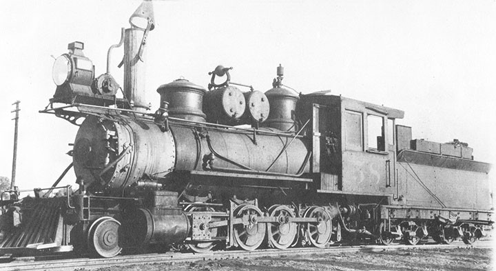
-Photo, collection R. Robb.
This project, now complete, has dragged out over 4 years with many starts and stops. I had never intended to write it up for the GAZETTE, but upon reflection there were many lessons I learned along this journey that could benefit others. Had I known these things in the beginning, it would have been a much easier task to create C&S #58. Through these pages I’ll share this knowledge with you, and I apologize for not taking better photos.
I’ve repaired and painted Sn3 models in the past, but I’d always started with complete models. What Don provided me was the basic carcass of an Overland model (likely C&S #65), bits of other C&S locomotives and a bin of detail castings. Foolishly thinking I had all that I needed, I dug into the project. Comparing the photograph to the parts I had on hand quickly showed that I was missing a lot of primary spotting features. The tender was close enough and didn’t require any modifications, but all the details on the boiler were wrong. Further complicating matters, was that all the detail parts I had on hand were replicas of late era C&S features which are very different from the earlier details.
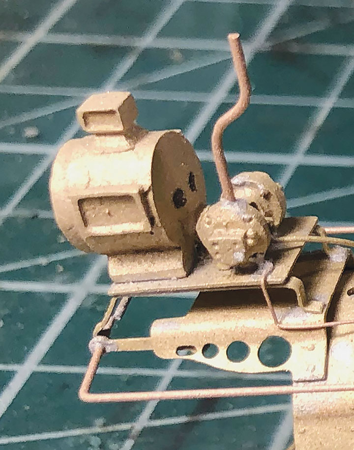
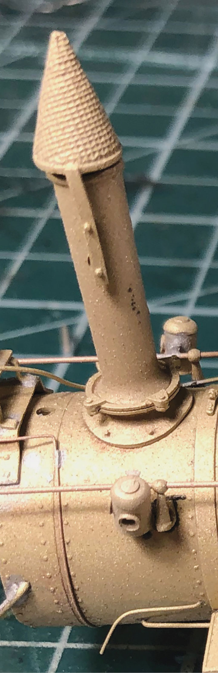
I started re-detailing the boiler with the headlight assembly. Using some of the detail parts I was provided, plus some brass stock and wire, I created a plausible rendition. Since it was integral to the assembly, I also fabricated new handrails. With the headlight complete, I set about installing the conical spark arrester.
With the easy work done, it was time to tackle the distinctive air tanks and domes. I searched all the sources I knew of, and even reached out to Jimmy Booth of P-B-L Models seeking suitable castings, but none could be found. I then ordered several Precision Scale Co. (PSC) brass castings in HO and O scale hoping something would be close enough to work. I struck out again. During this time, Don sent me a pair of white metal castings from Wiseman Model Services. I had hoped to keep this project pure with only brass parts and solder. I wasn’t convinced that I wanted to go with white metal ones. After even more searching, I gave up and shelved this project hoping I might stumble into brass parts at a future narrow gauge convention or someplace else.
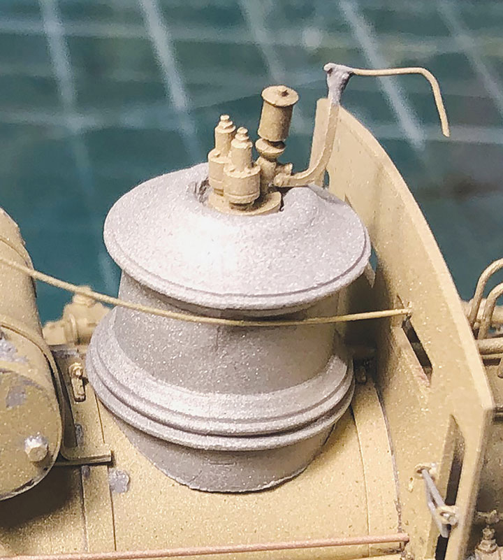
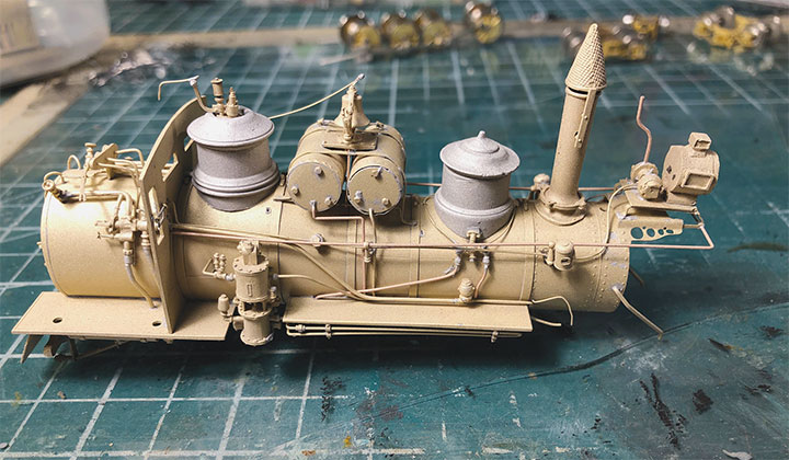
After a long wait and no new parts, I decided to give the white metal parts a try. I ended up having to cut the top off the sand dome and replace it with a top from another. With careful sanding, I managed to make this sectioning com-pletely hidden. Both domes were filed so they would conform to the circumference of the boiler and install without gaps. I’m aware that it is common for overseas modelers to successfully solder other metals than brass, but that was a skill I wasn’t anxious to teach myself. Instead, I chose to drill and tap holes in the bottom of the domes so they could be screwed to the brass boiler. I also wasn’t sure if these castings would survive my grit blasting and baking cycle that I use when painting brass locomotives. With the screws, I could remove the domes if needed.
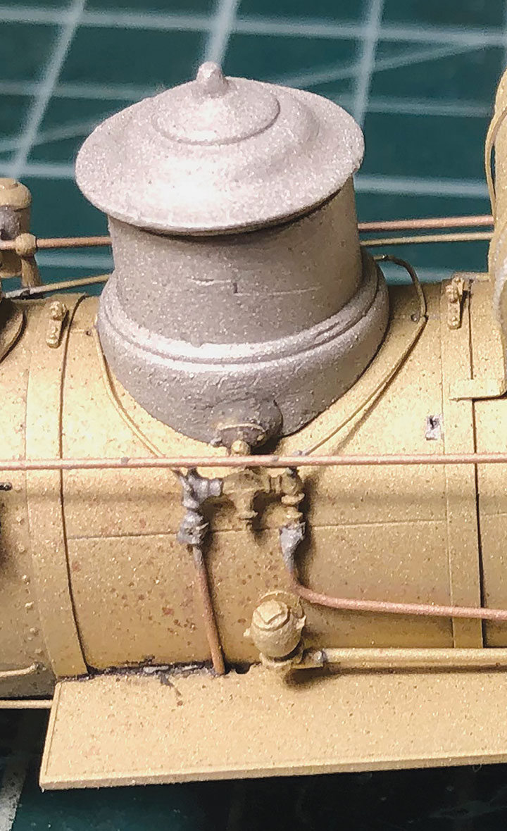
I reused the stock piping that loops around the dome, but the outlet valve and pipes to the wheels were fabricated from scratch. The valve piping was taken from the stock dome that came with the model. The pipes are just wire from my supplies. The valve and wires are soldered together, however they kept pulling the valve away from the dome. I ended up using JB Weld to glue the valve to the dome. This was after I found out that I could bake the JB Weld. In this photo it’s very hard to tell what is solder and what is JB Weld epoxy.
I still had one more problem with the domes. The sand dome was two pieces, and I wasn’t confident the screw would hold everything in place properly. I needed to glue the two pieces together. ACC and regular 5-minute epoxy will soften and loosen up with heat, so I didn’t want to use them for fear of the dome falling apart during my paint baking process. Because you can use JB Weld on gas engines, and they get hot, I decided to try that instead. I wasn’t positive this would work, so I experimented by using JB Weld to glue a brass casting to sheet brass and baked it far hotter than I normally bake brass locomotives. The JB Weld was completely unaffected by the heat. This turned out to be an excellent lesson for future projects. When baking other models, I’ve had them fall apart when, unknown to me, they have been poorly repaired by the previous owner using regular epoxy. TIP: you can remove epoxied parts easily with a soldering iron.
The last big challenge were the air tanks. These are so distinctive on C&S engines that I had to get this detail right. The problem I had was that none of the half dozen castings Don gave me were anywhere near close enough, and there was nothing else available. After putting the model away again for a long period of procrastination, I buckled down and tried scratchbuilding the tanks. I created a pair of air tank cores using K&S brass tube cut to the right length with the ends capped with brass sheet stock. These cores where then wrapped in .010-inch sheet brass with rivet detail along the edges. I punched the rivet detail with my Northwest Short Line Riveter. The tank wrapper seams are on the underside of the tanks where they won’t be seen. After successfully creating the air tanks, I set about detailing them with wire, Precision Scale Co. parts and a bell that I cut off another air tank casting. That completed my attempt at scratchbuilding my own air tank casting. With all the solder burn marks and other ugliness, I still wasn’t sure if I was successful, but I decided to solder the air tank assembly to the boiler and keep going with the project.
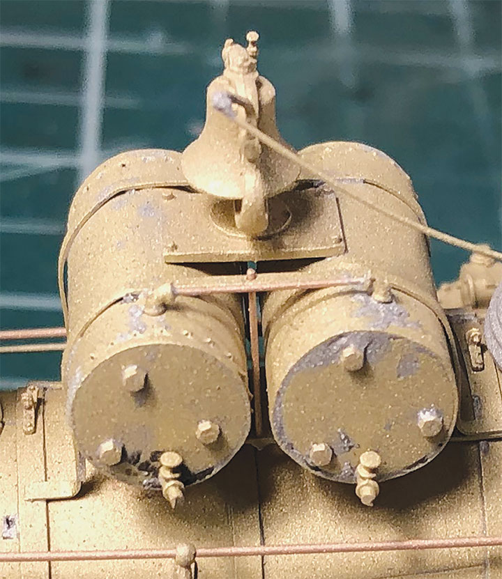
The actual tanks are K&S brass tubing with the ends capped with brass sheet stock. I created a .010-inch wrapper for the tubing. This wrapper was run through my NorthWest ShortLine Riveter to emboss rivets along the edges. I then wrapped the tubing and soldered the assembly together.
I used brass strip stock to create the straps that hold the tanks together and create the feet that hold the whole assembly to the boiler. One strap has the legs and wraps around the top and sides of the tanks. Another strap runs under the tanks and is soldered to the first at each end. Between the tanks I drilled, then soldered, a brass wire to simulate the tie rod between the straps. I left this wire “proud” of the strap to give the impression of having a NBW on the end.
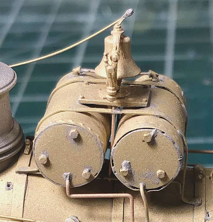
The ends of the tanks have hex bolts that I presume are the ends of tension rods on the prototype. I drilled holes in the tank ends and installed Precision Scale Co. hex nut castings into the holes. On the fireman’s side, there is a pipe on the top joining the two tanks together. I created this from wire and Precision Scale elbow castings. The fireman’s side also has Precision Scale globe valve castings to simulate the drain valves. On the engineer’s side, I used wire to plumb the tanks into the locomotives air system. The bell and its platform were cut off an Overland air tank casting and installed on my scratchbuilt tanks. Finally, a wire was added to simulate the bell’s rope.
While changing the air tanks and domes on the boiler, all the stock boiler piping was messed up or was in the wrong place. I used wire to form and replace many of the pipes. The sand dome has some sort of valve or piping casting at its base for connecting the distribution pipes. The castings I used lacked this, so I cut them off the stock brass dome that came with the model. With much struggling I managed to get these castings and their distribution pipes soldered together, however I couldn’t get the casting to sit tight against the white metal dome. Since my earlier heat test showed that I wouldn’t need to remove the domes during the painting process, I gave in and used JB Weld to make this connection.
At this point, the boiler assembly looked ugly, but all the main details were in the right places. I added brass marker lights hanging from the handrail to match the photo. A pewter toolbox in the parts bin, likely a Durango Switcher cab roof firebox casting, was cut to size and JB Welded to the walkway creating an accurate rendition of what was on the prototype. The whistle/pop valve was a brass casting that I JB Welded to the top of the steam dome. A whistle rope and other miscellaneous details were added to the boiler to finish it.
The windows on the stock cab weren’t completely accurate for C&S #58 in 1915, but were close enough, so I decided not to bother modifying them. The tender was very close to the photo, so no work was needed there either. The locomotive frame needed some tinkering to get it working properly, but no modifications were needed.
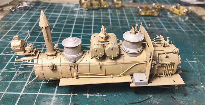
Not mentioned in the other photos, but on the fireman’s side you can see a modified white metal casting that I used to simulate the toolbox. This one was likely a casting for the Durango switcher firehose that I found in the parts bin. I just made it smaller, and it fit perfectly. It was also JB Welded in place.
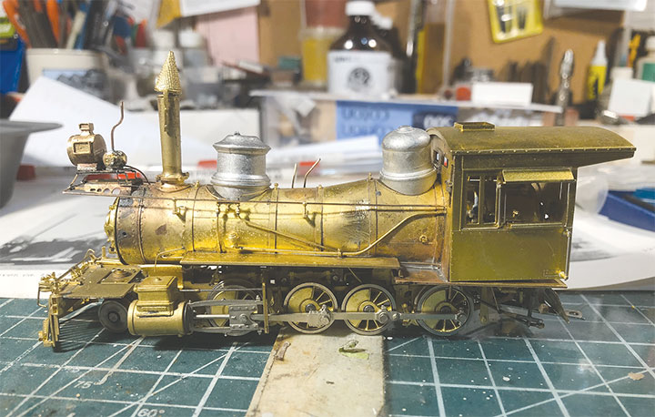
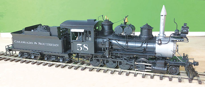
I then assembled the model with a feeling of accomplishment and a lot of trepidation. I had reworked this model more than any other in my modeling career. All the extra solder and burn marks made the boiler look downright ugly. Had I failed or succeeded? My grit blaster was going to answer that question. I disassembled the model for grit blasting and painting. I started blasting the boiler first. To my surprise and relief, it came out amazing! My amateur attempts at detailing looked nearly as good as any stock brass model. I was thrilled and motivated to push this project to the end. TIP: with care, a grit blaster is a great way to remove excess solder from brass models.
I ran the model through my usual paint process. The parts were masked and grit blasted. Then they were cleaned in my ultrasonic cleaner. Some masking is done, and the paint process began. I used a mix of ScaleCoat, Floquil, Humbrol, and Model Master paint on the model. The decals are from Thinfilm, and I baked the paint in my homemade brass cooker between coats.
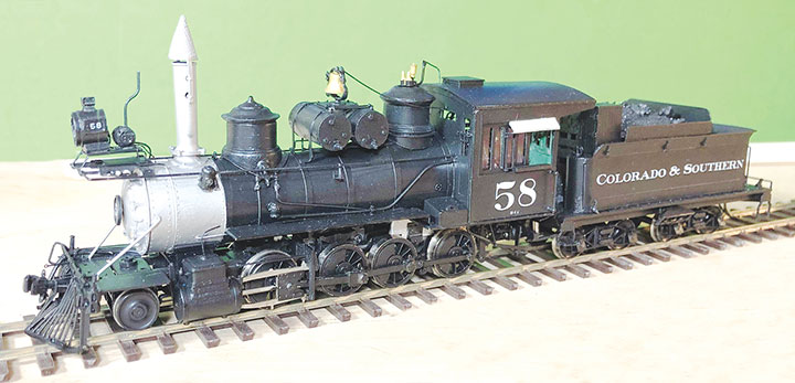
Don doesn’t have a layout and his fine models are in a display case, so I added a non-sound DCC decoder to control the motor and lights. An SMLED was used for the headlight and similar SMLEDS were used to light the marker lights. These were wired up on the white and yellow decoder wires. I programmed them using the programming track set-
up described in the January/February 2022 Gazette.
During the final assembly, I added glazing to the cab windows. An MV Products headlight was used for the headlight lens. The marker light lenses are just beads of Canopy Cement in the casting holes. The wires and blemishes were touched up and the project was complete.
This project was a long one but, in the end, I learned a lot and that knowledge will save me years (literally) on the next project. I learned that JB Weld can be used in place of solder without repercussions. I also learned that scratchbuilding in brass isn’t as hard as it might seem, especially when forced to do so. The last lesson was that I’m going to continue to enjoy modeling in my primary scale (HO) where detail parts are plentiful!
I hope you’ve enjoyed reading about this brass bashing project and picked up a few tips. Hopefully I’ve encouraged you to try what seems impossible. Heck, I even surprised myself with this project!