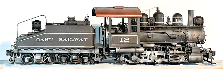
I was looking for a new locomotive project when a photo in Next Stop Honolulu by Jim Chiddix and MacKinnon Simpson caught my attention. A narrow gauge outside frame switch engine! Oahu Railway & Land Co.’s #12 is the kind of locomotive I like to build—a little bit different—something not seen on the more familiar Colorado narrow gauge lines.
Number 12 was one of four 0-6-0 switch engines owned by the Oahu Rail-way. I was only able to find a couple of photos of any of the little locomotives, however, #12 still exists. After years of working around the piers and pineapple canneries, it was the last steam engine retired by the OR&L. Fortunately it ended up in the care of the Hawaiian Railway Historical Society, who are preserving and restoring it. While the restoration is incomplete, the locomotive and its slope back tender are available for detailed research.
I contacted the Hawaiian Railway Historical Society to see if they could provide additional information on the engine. In a few days I got a reply from Jeff Livingston, who is the Society Historian, and a model railroader. He sent me measurements and multiple photos of the partially restored engine as well as several vintage photos of #12 when she was switching at the Honolulu docks. Without his help I would have never been able to build a credible model.
Finding the right drivers is the starting point for all my locomotive kit bashes and builds. The driver diameter on #12 was 38 inches. Checking on the available drivers in large scale soon narrowed the choice down to the 1:20.3 Bachmann outside frame consolidation drivers which scale out at 36 inches. Since the flanges are a little oversize, the appearance of the drivers, particularly when obscured by the outside frame, gave me an acceptable choice. The bonus of the axle already extended through the outside frame journal box made the choice even easier.
I had planned on cutting down the frame of the Bachmann 2-8-0, but after I examined it in greater detail, I decided it wasn’t what I wanted. Scrounging around in my scrap pile of locomotive parts left over from previous kit bashes I found an Accucraft C-21 frame. It had possibilities. By cutting and splicing, I was able to reduce the frame from four axles to three, and come up with a frame with the correct axle spacing. Extending the front of the frame and cutting down the rear gave me an accurate starting point.
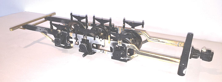
The journal boxes on the Bachmann drivers fit the Accucraft frame very nicely. The counterweights on the Bachmann drivers were removed and ground down from their fan shape to the rounded contour of the prototype. After testing the Bachmann motor and gearbox, and finding everything running smoothly, I removed them so that the wheels and rods could move freely during construction. With a good foundation I was ready to go on to the rest of the project.
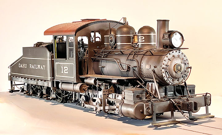
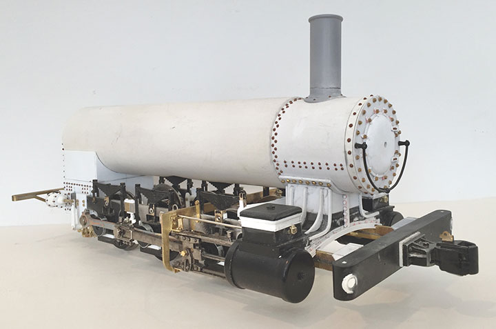
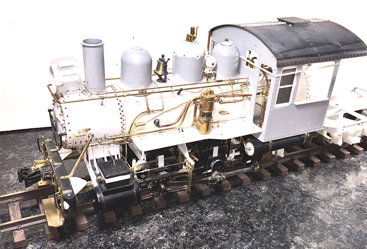
The boiler is a piece of PVC which turned out to be almost exactly the correct diameter. A second piece of PVC, fit into the front of the boiler and wrapped with some styrene, brought the smoke box up to the correct diameter. I used the Bachmann cylinders as a starting point for the steam chest. Left over side rods from the C-21 were cut and spliced appropriately.
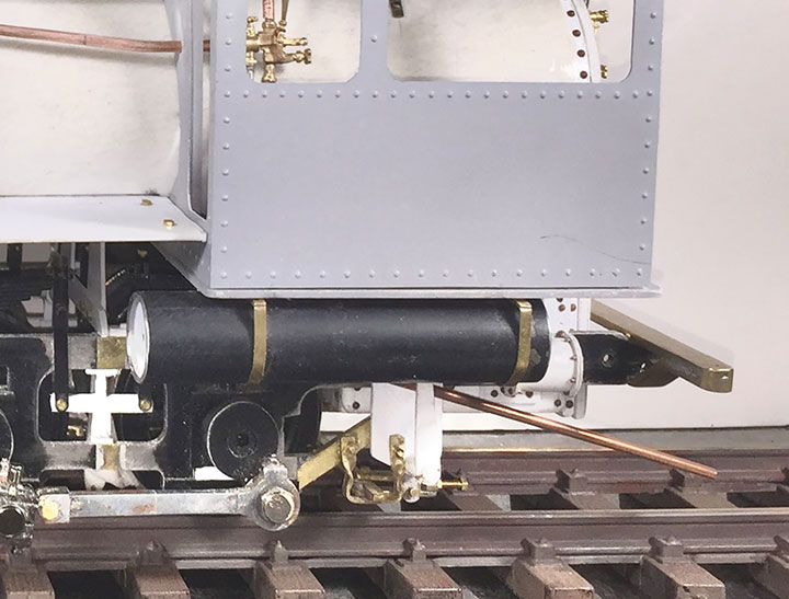
I decided to use the Bachmann cyl-inders because they were the correct width to align with the main rods on the drivers. The Bachmann driver journals hold the counterweight and the rods a little further away from the frame than the prototype. The distance between the cylinder’s piston center line on #12 is 84 inches. The Bachmann cylinders scale out at about 88 inches. Not noticeable until the air tanks under the cab were put in place. The cab was built to the correct scale width. So, the air tanks were each about a 32nd of an inch too close to the side rods. The rods would bind against the air tank. To solve this problem, I ground away a small portion of the inside of the tank. Fortunately, it is not noticeable from the outside. The final clearance is only a few thousandths of an inch, but enough to let the rod move past the tank. The original air tanks are no longer on the engine, but rod clearances on it must have been tight as well.
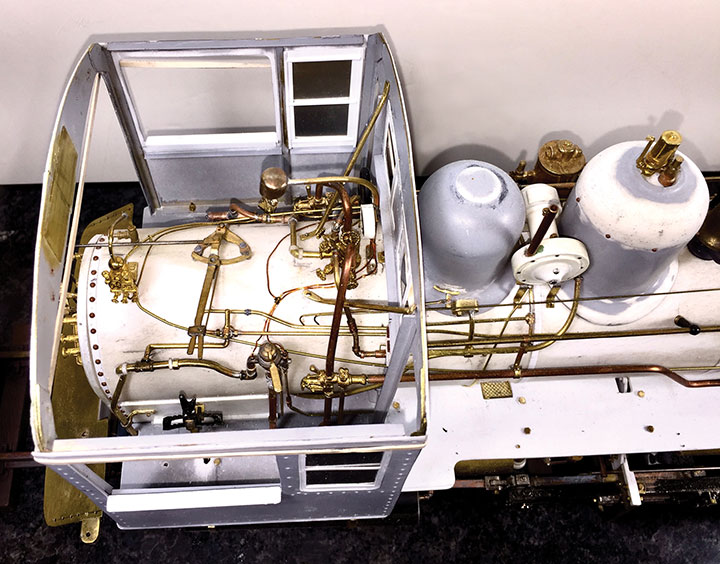
The cab interior was a mystery. The throttle linkage is still in place on the engine, but almost everything else has been removed. In many cases, the only clue as to what was previously in the cab is a hole in the wall or in the floor or a bolt sticking out of the boiler. With the large open doorways and windows and the wide-open rear deck, the boiler and back head needed some detail. After the throttle and reversing lever were placed, Westinghouse diagrams from various reference books were used to assemble a reasonable arrangement of the air brake piping, brake stand and other air lines. From the photos of #12 taken many years ago, the turret and steam piping could be approximately placed in the cab with the various exterior lines to the generator, air compressor, and steam blower, matching the photos.
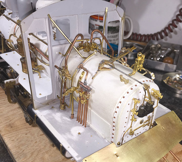
In the present state of restoration of #12, there is nothing to indicate how the piping of this oil-fired engine was arranged, and sadly the old photos didn’t offer much help. Oil firing requires various steam lines and valves to move the oil from the tender, heat the oil and inject it into the firebox. There was usually a pipe from the steam turret to a manifold from which various steam lines were directed to the tender, oil heater, and oil injector. In addition to the oil firing valve, there were various damper controls that the fireman used to tend the fire. Following photos and diagrams of similar oil-fired engines, I built up a collection of pipes and levers. I make no claim that it is accurate for OR&L #12, but it would work the way I built it.
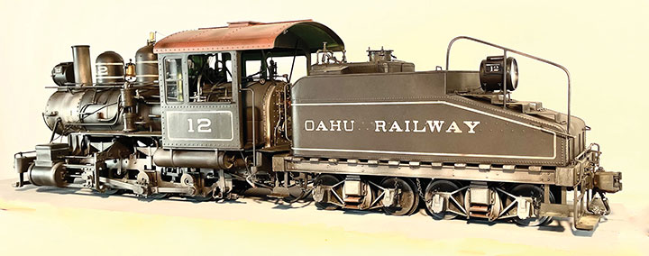
Once the engine was near completion, I turned my attention to the tender. The slope back tender was one of the things that attracted me to #12. Again, starting with the wheels, I began looking for the parts I needed. The tender wheels were 26 inches in diameter, and I had some scale 26-inch wheels on hand. The truck frames were unlike anything available. With the known wheel diameter, the dimensions of the truck side frames and bolsters could be determined by proportions using photos. Patterns for the component parts of the trucks were fashioned and used to make a mold. Resin castings of the various parts were made, and the trucks assembled.
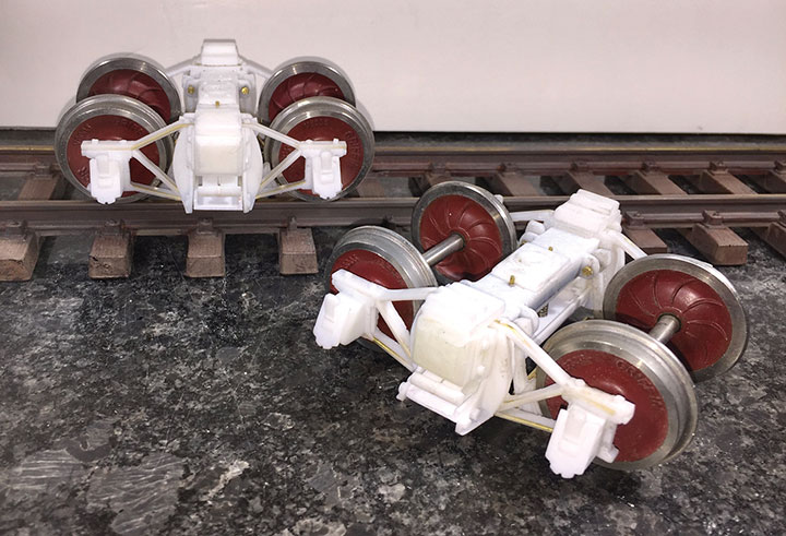
in the side frame castings to provide extra strength.
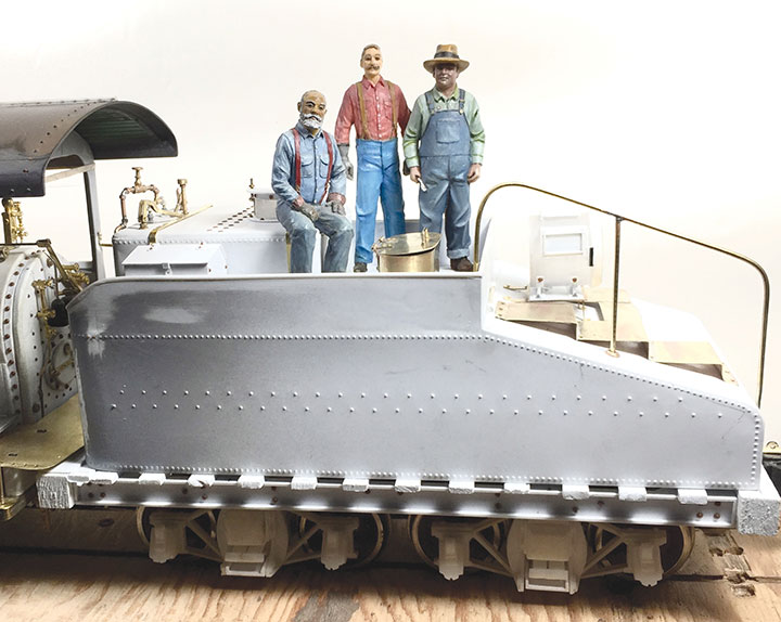
Corner steps, grab irons, foot boards and cut levers were added to the tender frame. Like the cab, the exact brake rigging is unknown, but an appropriate brake cylinder, reservoir tank, triple valve and piping were installed, and the main brake rods connected to the truck brake levers.
The engine and tender were thorough-ly cleaned to remove any oil, as well as metal and plastic shavings and dust. I used ScaleCoat Engine Black enamel as a base coat. The finishing touch were the decals. Stan Cedarleaf of Cedarleaf Custom Decals came up with the perfect lettering font as well as all the pin striping, ALCO builder’s plate and number plate decals. After sealing the decals, mixtures of various MIG acrylics were used for weathering.
A 14.8-volt battery is mounted in the tender to power the locomotive. I used an AirWire CONVRTR-25 and a Tsunami2 sound decoder. Speakers were placed in both the locomotive and tender. Lighting, including cab lights and firebox lighting, are LEDs.
With some truck chains plus hoses between the engine and tender, my model of Oahu Railway & Land Com-pany #12 was complete. Despite a few mistakes and some guessing along the way, I think the end result is close to the spirit of the OR&L locomotive. One of these days I’d like to visit Hawaii and check out the real #12. In the meantime, I’ve got a neat little switch engine to run.