Some Background
Many clubs and individual modelers have gone to great lengths over the years to faithfully duplicate the operation of prototype railroads, and while this can be a fascinating aspect of the hobby for some, the paperwork and other complications needed to accomplish it have never really appealed to me. I want to move traffic on my layout in a logical and reasonably realistic manner, but simplicity is always in the forefront of my mind. In fact, one of the reasons I finally retired after a 40-year career was the increasingly burdensome paperwork I had to deal with. If I didn’t like it at work, I certainly wasn’t going to go out of my way to generate it in my hobby!

As an example of simplicity in action, the article on my On30 Bear River Railway & Canal Company switching layout in the July/August 2020 GAZETTE outlined a very basic operating system that involved placing colored pins on cars and industries to determine how cars were to be moved around the layout. That layout is so small (35 x 64 inches) that I believe anything more sophisticated would have been pointless.
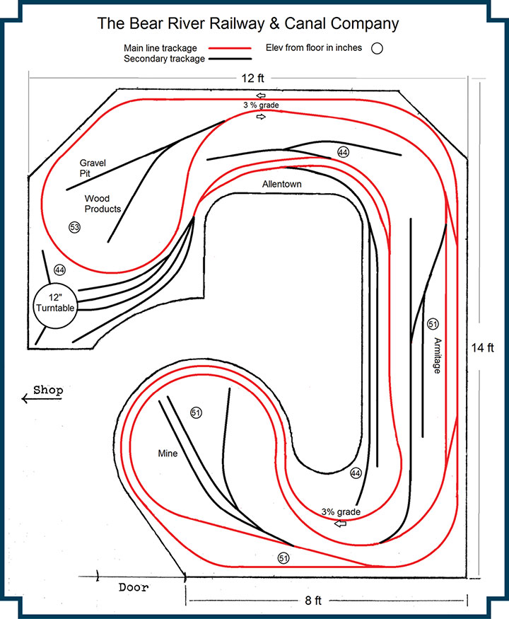
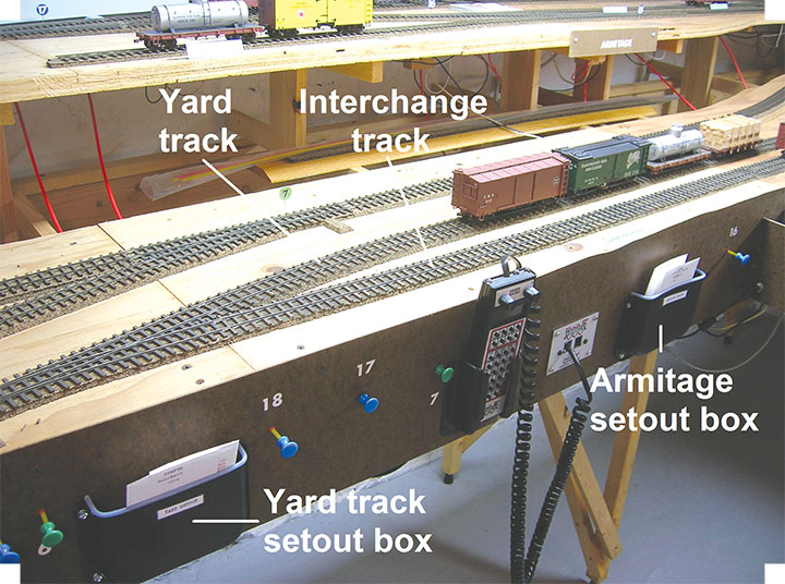
However, another On30 layout I am working on is larger, and I thought it could benefit from a more advanced operating system. The layout was designed for out-and-back operation, on two levels. Allentown, on the lower level, is the terminus from which all trains originate, and to which they all return. It has an engine servicing facility, a storage yard track, a station, a team track, and a few other industries. A major focus is the interchange track, the railroad’s connection to the outside world. All of this, of course, is modeled in quarter-inch scale in a limited space, so important as it is, the interchange track takes up very little room on the layout. It is merely a spur shared with two other industries, and in fact it is an “aisle industry,” with only a platform on the edge of the bench work that faces an imaginary standard gauge interchange track located off-layout in the operator’s aisle.
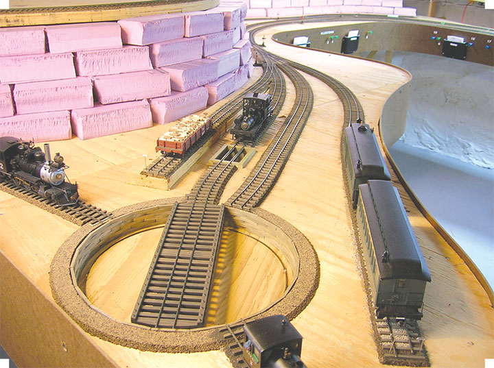
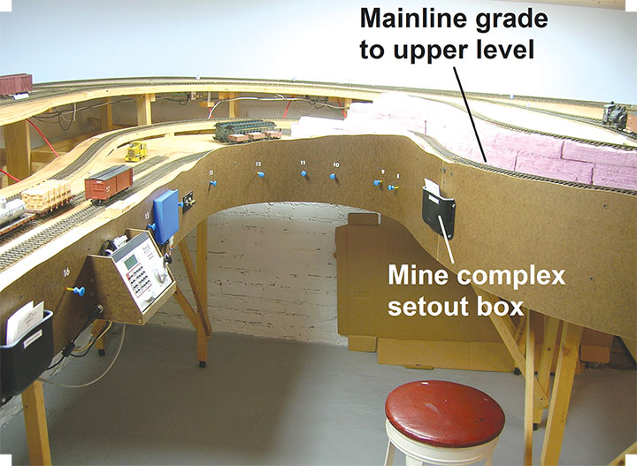
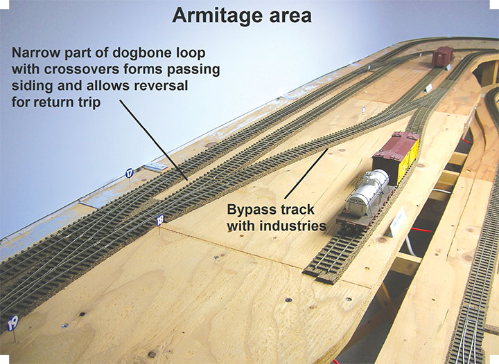
The upper level consists of a central town (Armitage) with an oil/fuel dealer, a station, a team track, and two other more remotely located industrial areas: an ore mining operation enclosed in a loop on what I have defined as the southern end, and a forest products company plus a gravel pit operation enclosed in another loop on the northern end. Supplies coming up the hill from Allentown and the outside world support the people and activities at these upper-level locations, and products from the industries there are shipped out to other places on the layout or down to the Allentown interchange and points beyond. A loop on the upper level permits continuous running to extend mainline distance, or just to allow enjoyable train watching. This loop, in combination with the arrangement of crossovers at Armitage, also allows the train to reverse direction before heading downhill again to complete the “turn.” The photos here illustrate some of the locations described, as well as emphasizing the two-level construction of the layout, something that may not be clearly apparent in the track plan. As you can see from the photos, unlike my small switching layout, this layout is currently bereft of scenery, since operation and a variety of workbench projects have been my main focus up to this point.
Incidentally, at twelve by fourteen feet, this is probably one of the largest “cookie-cutter” layouts around. While working on the basic L-girder bench work, I chanced upon a large quantity of free half-inch plywood. I laid it out on the L-girder joists in a double thickness, crossing the grain and overlapping the joints between layers. As I went along, I glued and screwed the two layers together, producing what is in effect a single huge sheet of plywood one inch thick. After cutting the plywood as needed to produce the layout’s final shape, I laid down a good amount of the track while everything was still flat and easy to work on. Then I jacked up the upper level a little bit at a time, adjusted the grades, and finally secured everything to bench work risers.
Operation
After all track was laid and operation became feasible, I began experimenting with an operating system that would generally represent prototypical operation, but still be simple enough to keep me from being frustrated by self-imposed bureaucracy. Needless to say, this particular wheel has been invented many times, in many forms, and by many people before, and anything I came up with would inevitably be built on what others had already done. In particular, what I describe here owes much to the car card and waybill system described by Malcolm Furlow in his article, Operation on the San Juan Central, in the August 1984 Model Railroader. (Also available from Benchmark Publications, see page 96.) If that article is available to you, I recommend it as good background information. In some respects, my variation of his system is a bit simpler, but in other places it adds a few wrinkles. I expect other modelers who choose to play with it will make their own modifications. I think it can be adapted to almost any layout possessing a capacity for mainline way freight operation and having multiple locations for switching.
As designed, my layout could accommodate three operators, representing a mainline crew running trains between the two levels and switching crews and locomotives permanently assigned to each end. Being the only model railroader in my local area, however, I reduced my system to work with a single operator and locomotive, integrating the work of the three crews into a sequence of operations spread out over a period of hours, or often, several operating sessions. A slightly more sophisticated version might retain the switching locomotives on the two ends of the layout, with the single operator running each of them in turn to accomplish their tasks. This is where the individual modeler’s creativity comes into play.
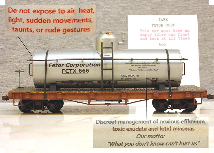
In any case, paperwork is limited to the initial creation of a car card for each car on the layout, plus an imaginative variety of waybills for the various “industries” (any place where a car can logically be spotted), including such non-revenue locations as the locomotive fueling track at the Allentown engine terminal. Obviously, team tracks and the interchange track can accommodate a wide variety of car types without raising eyebrows, but with a little imagination, even fairly narrowly focused industries can justify atypical cars once in a while. For example, a refrigerator car might occasionally be sent to the forest products company to provide ice and refreshments for the company picnic. Another interesting twist can be added by requiring certain cars to be given special treatment. This is common on the prototype when cars are carrying a variety of hazardous cargoes, although my tongue-in-cheek example here is a bit extreme (see bottom photo on page 33), even for the less-regulated early 20th century era I am modeling.
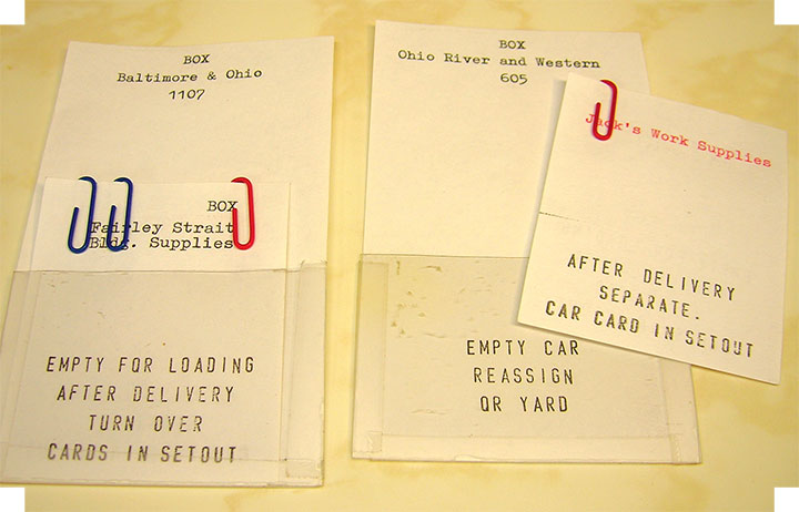
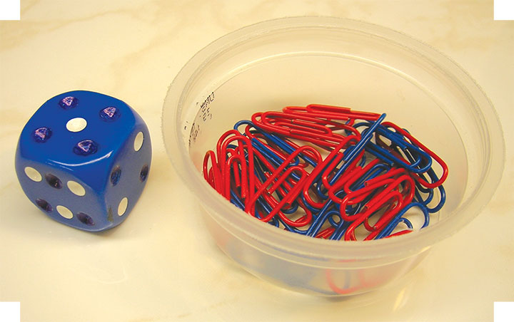
The car cards and waybills are pretty much the same as described by Furlow, but there is one major change. Since, in the real world, cars are not always moved in the next train after being delivered because industries often take more than one day to load or unload a car, I added colored paper clips to the waybills to indicate how many days (operating sessions) a car is to remain spotted in a given location. Blue clips determine the time the car spends at its first stop for loading, and red clips indicate how long the car stays at the location where it is to be unloaded. This adds interest to switching operations because the extended-stay cars have to be shuffled about and worked around as new cars are brought in, and others behind them are removed. The number of clips of each color on each waybill is determined by rolling a die that has been modified to turn up only ones, twos, or threes. There are three ones, two twos, and one three on the die, making shorter stays at an industry more likely than longer ones.
Each of the towns and switching areas has a setout box on the fascia to hold car cards and waybills for the cars currently at that location. The Allentown yard track is given its own setout box for cars without waybills, waiting to be assigned to trains. Another wrinkle I added to Furlow’s basic idea was reassigning empty cars “on the fly.” Furlow had cars that had been unloaded by consignees sent back to the yard before being assigned to another train. In real life, a railroad might instead send that empty car to another industry farther down the line that is in need of it, rather than putting unnecessary and unproductive miles on it by returning it to the yard first. So, when looking for a car to send to an industry, I first look for car cards without waybills already located in setout boxes along the route the train will be taking. If an empty car of the right kind is found, and if the industry needing such a car will be encountered later as the train proceeds on it’s run, the waybill will be attached to that car card and the car will be picked up and then later dropped off at the new location.
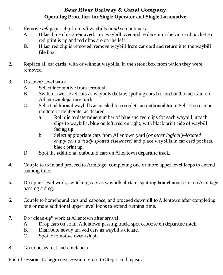
To initialize the system, all the cars on the layout were moved to the yard/storage area at Allentown. I then established an initial car distribution around the layout by beginning with step 3(C), on the operating sequence shown in Figure 2 above. I continued “priming the pump” like this as much as needed to get the layout populated with cars. I found that following this 3(C) procedure in the beginning is crucial, because except for cars in the yard, there shouldn’t be any cars scattered around the layout without properly assigned waybills in their card pockets. If there are, confusion will reign. Along this same line, if I swap cars between layout and storage, I make sure that new cars are placed only in the yard, with accompanying car cards, and that old cars are taken only from the yard, and that their car cards are retired along with them.
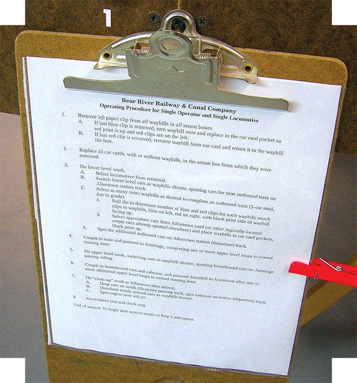
Once this initial distribution was accomplished, actual operation proceeds by repeatedly cycling through the complete sequence starting from step one. The system is now self-perpetuating, as the addition of new cars to outbound trains in step 3(C) continuously replenishes the road’s traffic as empty cars are brought back to the yard. Since the complete sequence may stretch over several operating sessions depending how much time I want to spend on it, I hang a clipboard on the layout with the operating sequence attached to it, along with a clothespin acting as a marker that can be moved down the list to remind me where I was when the last session ended.
Obviously, the procedure shown here was developed specifically for my own layout. If you choose to emulate it, locations and other details will be altered to suit your own situation, but the basic system should work in a wide range of circumstances. More importantly, my experiments may inspire you to take off in an even more creative direction. Have fun with it!