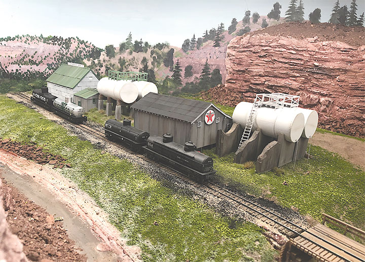
In the previous two issues of the GAZETTE I described how I built HO models of the Conoco and Texaco petroleum distributors at Old Placerville, Colorado. I’ll continue the story by describing how I built the tanks for both distributors and how I blended the structures into my layout. Please follow along with the photos and see how I accomplished this.
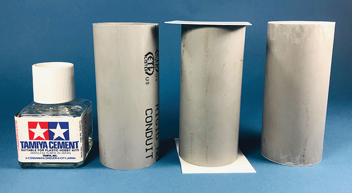
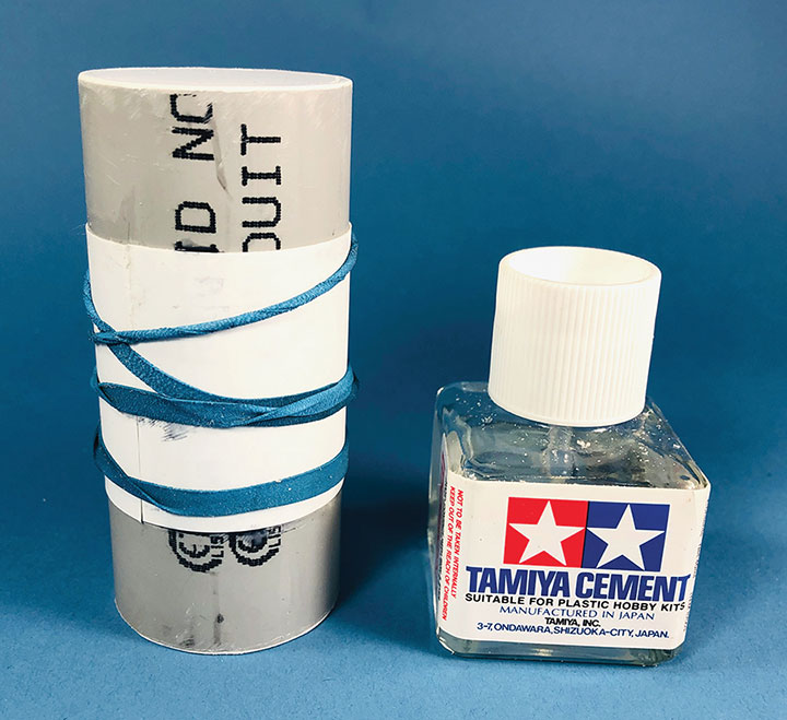
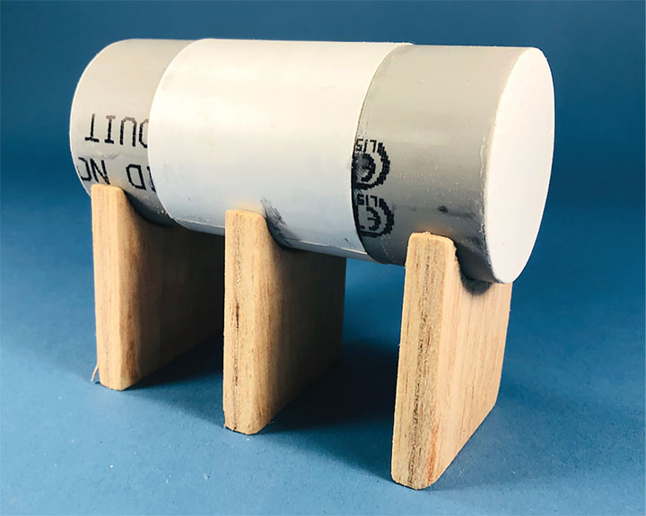
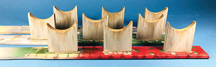
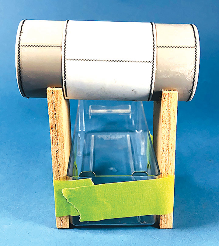
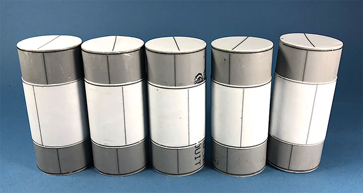
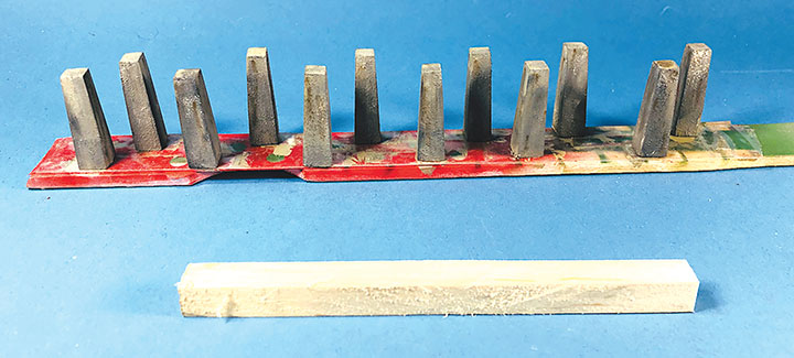
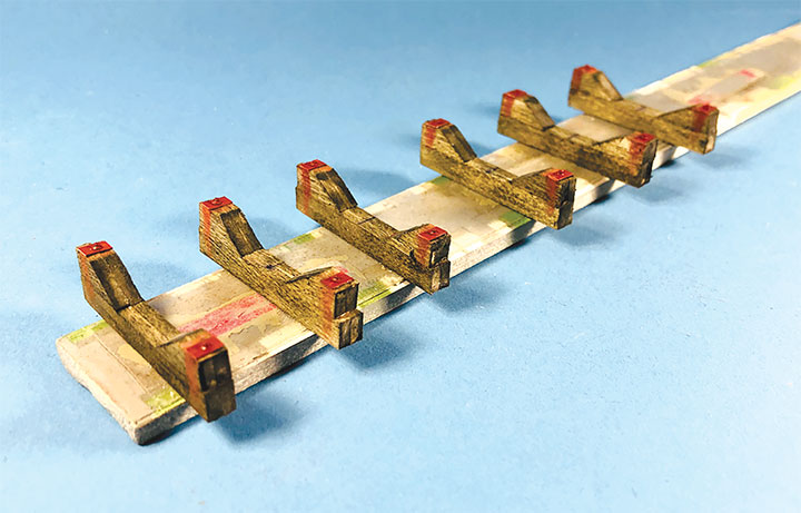
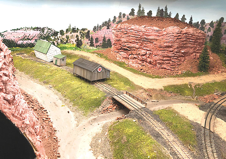
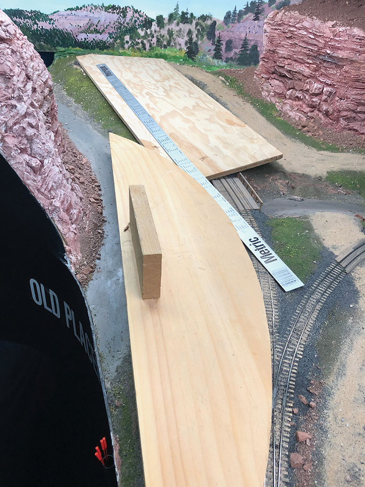
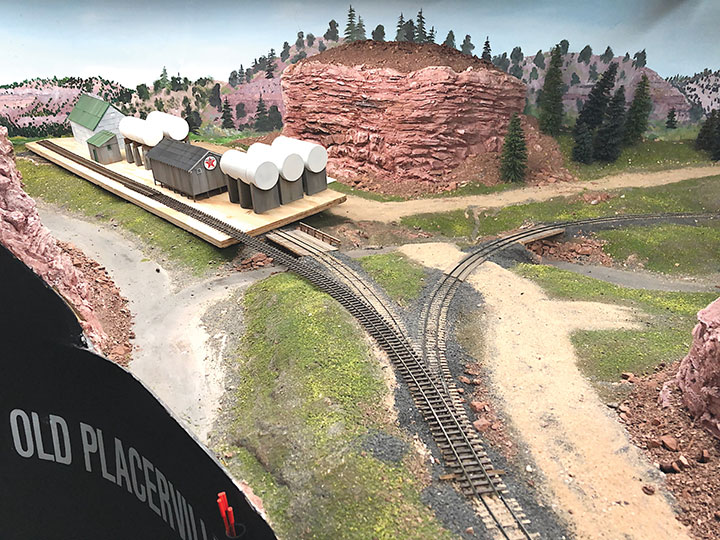
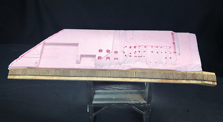
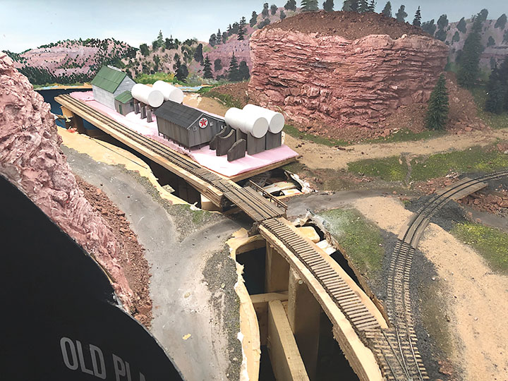
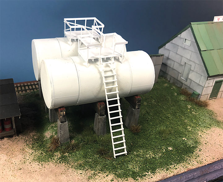
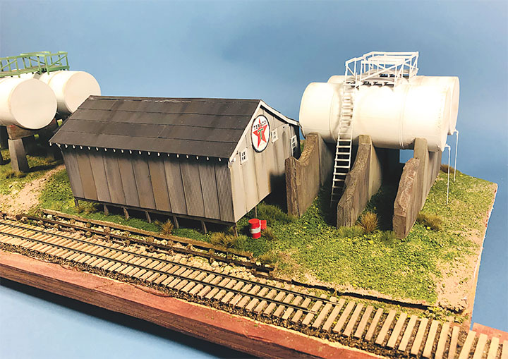
I built the entire petroleum spur at my workbench, including the scenery. This diorama replaced an existing spur on my layout and was blended into the basic scenery. With the Conoco distributor in place, I now have a destination for my San Juan Models tank cars. The Texaco dealership provides me with a destination for my CYCX numbered narrow frame tanks as well as my double dome TCX tanks. The people of Placerville and the adjoining Paradox Valley will be well served for their petroleum needs.Initially I tried making the tanks using a styrene sheet wrapped around styrene disks, but all I managed to accomplish was to create a badly dented tank that looked like it was being crushed in a junk yard. That failure sent me back to the drawing board. After some thought, I took a trip to the local home improvement store and bought a length of 1¼-inch diameter plastic conduit. The outer diameter worked out almost perfectly to the 12 feet indicated on the Mike Blazek drawings (www.blazekplan.com) that I was using as a guide. I cut five pieces of conduit to 27 scale feet in length, then capped the ends with .020-inch styrene. I used Tamiya cement which seemed to work just fine with the plastic that the conduit was made from. The caps were trimmed to size and filed to create a smooth union. This photo illustrates the steps involved.Most prototype tanks constructed in the early 1900s were made by riveting a number of rolled steel sheets together. To simulate the center section of sheets I wrapped a 13½-scale-foot wide piece of .010-inch styrene around the tanks. More Tamiya glue and rubber bands held the styrene in place.The three Texaco tanks sat on top of poured concrete saddles. I used 5/16-inch plywood to simulate these saddles. The first step was to cut the plywood into strips that were a scale 12-feet wide. I then drilled 1 5/8-inch holes about three real inches apart. Then I cut through the middle of each hole creating a bunch of blocks of wood with a half a circle cut out of each end. These were then used to create saddles ten scale feet in height. When I was done, I had a pile of concrete saddle forms. I selected the best-looking ones and grouped them in sets of three saddles for each of the three Texaco tanks. The wood was then sanded smooth, and I ended up with basic forms that were used to simulate the real concrete saddles.The three sets of Texaco tank saddles were painted a base coat of Floquil Concrete. To create texture and make the wood blocks look more like concrete, I rubbed on three shades of gray Pan Pastels that ranged from an almost white tone to a medium gray. I then used an earth-colored Pan Pastel and various rust colors to add streaks to the concrete saddles. When I was satisfied with the look, I sprayed them with Testors Dullcote.With the Texaco tank saddles sorted out, I focused on finishing the tanks. I felt they needed more detail, so I used Archer textured rivets decals (AR 88098 & AR 88031) to simulate the seams in the tank pieces. I also added a row on the tank ends to simulate two pieces of metal making up the ends. These rivet decals were tricky to apply to a cylinder until I used some left-over tank saddles taped to a plastic box as a cradle. This setup made it much easier to apply the decals.I made the Texaco and Conoco tanks identical. There is one photo in the RGS Story Vol. 1 (Sundance Publications) that shows the Conoco tanks in the background, and they appear to be about the same size as the Texaco tanks. This made construction a lot easier. With all the Archer decals applied, I had all five tanks ready for paint. I ended up painting them Floquil Reefer White shortly after this photo was taken.In the RGS Story Vol. 1, if you look closely at the photos of the left-over tank bases for the Conoco facility, you’ll see tapered concrete pedestals. To create these pedestals, I used my table saw to cut basswood 3-scale-feet square. I cut this wood into 10-scale-foot lengths. Placing a 2-foot-square mask over the end of each pedestal blank, I traced a 6-scale-inch outline on the perimeter of the end of the wood blocks. Using a belt sander clamped in my workbench vice, I sanded the four sides to a taper using the 6-inch mask as my guide for making one end 2-feet square while leaving the other end 3-feet square. When I finished making these pedestal blanks, I painted and weathered them using the same technique as I did for the Texaco tank saddles.The prototype photos only show the Conoco concrete tank pedestals but don’t show any details of what the tanks sat on. Since there is no sign of steel bracing in the photos, I felt that there was probably some sort of wooden frame between the pedestals and the tank. Using 8- x 16-inch scale lumber, I created large cradles like what you’d see on a Conoco tank car. These cradles were stained with Hunterline Driftwood and Medium Brown stain. On the prototype, the cradles would have needed to be fastened to the pedestals. To simulate that, I made metal plates using 1- x 10-inch styrene with Grandt Line #5123 NBW castings to make it appear like the cradles are lag bolted to the tops of the concrete pedestals. I weathered these cradles with rust colored Pan Pastels.With the basic structures built, I wanted to see how they would fit on the existing Old Placerville vspur on my layout. I didn’t bother with the tanks, but set the other structures in place while leaving room for the tanks. I wanted to get a sense for how everything would fit into the scene, verify the elevations, and see if I could utilize the existing spur trackage. It was apparent that space was going to be tight, and the spur would need to be moved to make room for all the buildings.With the general position of where the petroleum distributors would fit into my Old Placerville scene decided, I did one more re-check of the scene with the buildings in place. I also used pieces of flextrack to determine where the spur would be aligned. Once the buildings were in place, it became apparent that I didn’t have enough room for the Texaco tanks. On the prototype, they were further to the right and not blocking the end of the building. If I moved them in the scene, I wouldn’t have room for the highway that ran behind the distributors and my petroleum customers wouldn’t be able to access these distributors. Looking back at the prototype photos I could see that at least one of the Texaco tanks was removed and crumbling concrete saddles were left in its place. I decided that a fair compromise would be to have only two Texaco tanks and replace the third with crumbling tank saddles in front of the building. Using some left-over saddles, I cut them up to make them look like they were crumbling away and painted them to match the others. This helped control the depth of the scene and left room for the highway.I cut a piece of plywood roughly the size of the area where all the buildings would fit while leaving room for the spur track. Installing the spur track at the workbench would be the way to go. This part of my layout is so deep that I can’t reach the very back of the scene, let alone hand lay track back there. In this photo, I’m using the meter stick to visualize the center line of the spur track. The wooden block in the photo has a 24-inch curve cut into it. I used this gauge to plan my layout long before the advent of “sweeps” for simulating radii. Nearly all my curves have a 24-inch radius or greater curve. With the gauge and ruler in place, I could see where I needed to re-construct the scenery and track.I used ½-inch foam to create contours under and around the structures and tanks and used a foam hot cutter to contour the land, cut in the areas where the buildings were set into the hillside and add holes for the foundations to find level ground. You can also see that I’ve added ties for the future spur track.I did one last fitting before I started on the final scenery. The old scenery has been removed in this photo and supports (not seen) for the petroleum distributor scene have been installed in the bench work. All the buildings are set in place and concrete ruins replace one of the Texaco tanks. I’ve also spiked rail along the spur. The sub roadbed and ties have also been installed on the layout and the bridge has been relocated.I added sanded grout and ground foam to the scenery base after setting the buildings into their final position. Once the tanks were fully glued to the diorama base and being careful not to get glue on the tanks, I built the tank walkways in place. These walkways and ladders were built using various sizes of Evergreen Styrene.This is the trackside view of the Texaco distributor set into the diorama base. The tank walkways have been built out of styrene, painted Floquil Reefer White and set in place. Precision Scale #2935 Valves and .020-inch wire have been added to the ends.This is the highway side view of the Conoco distributor. The buildings have been set into the scenery and the tank walkways have been installed. The walkways were painted Humbrol #78 Green and weathered with Pan Pastels.This is the completed Texaco dealership as seen from the highway. Unfortunately, all this detail will rarely be seen on my layout since it faces the backdrop.This trackside view of the Conoco distributor has been sceniced on my workbench and is ready to install. I didn’t bother adding ballast to the spur since it will be on a grade on my layout but sits flat on my workbench.The scenery is roughed in, and this project is completed for now. In the future, I’ll add more details and scenery.
\\