Some Background
There is a section of central Pennsylvania in Centre County known as the Barrens. It’s a wooded area of some 9,000 acres first inhabited by the Shawnee Indians. It is believed that they gave the area its name because their crops would not grow very well in the sandy soil. The Commonwealth of Pennsylvania purchased this and surrounding land from the Shawnees in the 18th century. The Commonwealth explored and surveyed this area of Centre County to define parcels that would be sold to landlords and homesteaders. In 1784, one of the surveyors discovered an outcropping of iron ore in the Barrens; further searching turned up immense and widespread deposits of the ore. In the late-18th and 19th centuries, iron ore was of greater value than gold to Pennsylvania’s ironmasters. There were over a dozen blast furnaces operating in Centre County alone. The Barrens did not have the only ore banks; they were being discovered all over the region. Large and small mining operations and the production of pig iron changed the physical and economic face of the area.
The River Hill bank (open mine) located in the Barrens was the most dependable source of iron ore in the county. In 1880, forty-five-year-old Andrew Carnegie traveled east to secure ore supplies for his expanding Pittsburgh operations. He was impressed with the ore being mined at River Hill and eventually purchased it from Moses Thompson, the ironmaster from Centre Furnace, located just east of present-day State College, Pennsylvania, and Penn State University. Carnegie named the area Scotia, after his native Scotland. Workers, and a community to support them, were needed to run Carnegie’s new mining operation called the Scotia Iron Works. By 1883 he had the Lewisburg and Tyrone Railroad (L&T) extend its tracks into Scotia so that heavy equipment and materials could be brought in to build a very large ore washer; one based on the 1842 invention by Abraham Valentine of the Valentine Iron Company located in Bellefonte, Pennsylvania. This design was simple and inexpensive. The washer itself consisted of a steam-driven shaft with attached cast iron spikes. This shaft acted as a screen which was placed in a trough with running water. As the spike shaft revolved, the ore dumped into the trough came out the other end fully cleaned of the clay and sand attached to it when mined. Wells were dug close to the washer to supply the water. Steam-powered pumps were used to lift the water to five elevated water tanks. The tanks on the towers were higher than the washer trough.
The mines at Scotia were not underground mines, but open mines, or banks. At first, all work was done with picks and shovels and horses and carts. Stock was dug, loaded onto carts, and hauled to the ore washer. The cleaned ore was eventually loaded onto L&T gondolas for transport to Tyrone, Pennsylvania, where the gondolas were transferred to the Pennsylvania Railroad (PRR) for shipment to the Pittsburgh mills. The average output was two railroad cars per day. To increase production, Carnegie purchased three newly invented steam shovels, and built narrow gauge railroads from the ore washer to the open mines. The steam shovel buckets could hold a cubic yard of iron-rich clay and would load from 600 to 1,100 cubic yards per day. The 0-4-0 dinky steam locomotive could haul up to 24 loaded ore cars to the ore washer. The cars were uncoupled at the base of the washer and a steam-driven hoist system was used to pull them one-by-one up an inclined ramp to the washing trough. These technical improvements resulted in an average of 15 to 18 gondola cars full of ore being shipped to Pittsburgh daily.
In the 1880s, there were well over a thousand steel plants in the United States. Bigger companies were buying up the smaller ones. Andrew Carnegie led the conglomeration movement by forming the Carnegie Steel Company in 1882, making Pittsburgh the steel capital of the world. In 1898 J.P. Morgan challenged Carnegie’s monopoly by forming the Federal Steel Company in which two Pittsburgh steel companies were included in the buyouts. As Carnegie was ready to retire, and Morgan was undercutting his prices, Carnegie sold The Scotia Iron Works to the Bellefonte Furnace Company in 1899. This company closed the Scotia mines in 1914. The two steel companies owned by Carnegie and Morgan eventually merged to form U.S. Steel in 1901. Charles Schwab was chosen as its first president; two years later, Schwab founded the Bethlehem Steel Company.
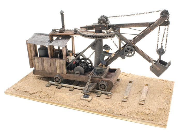
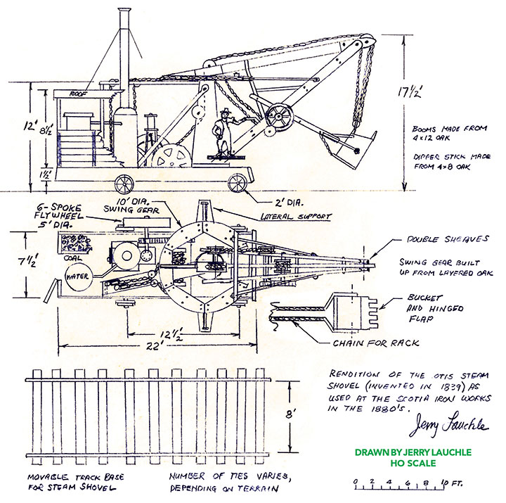
The steam shovel played a large part in Carnegie’s mine operation at Scotia. The steam shovel, or excavator, was invented by William S. Otis who received a patent for his design in 1839. They were built on a wooden chassis on which the boiler and engine were mounted. The shovel arm was mounted at the other end of the chassis. Four flanged wheels on axles supported the chassis. Temporary rail tracks made from either wood or metal were laid by workers where the shovel was expected to work. It is believed that in Scotia, mules were used to move the excavator on its tracks as well as to position the ore cars for loading on the narrow gauge railroad tracks that were laid nearby.
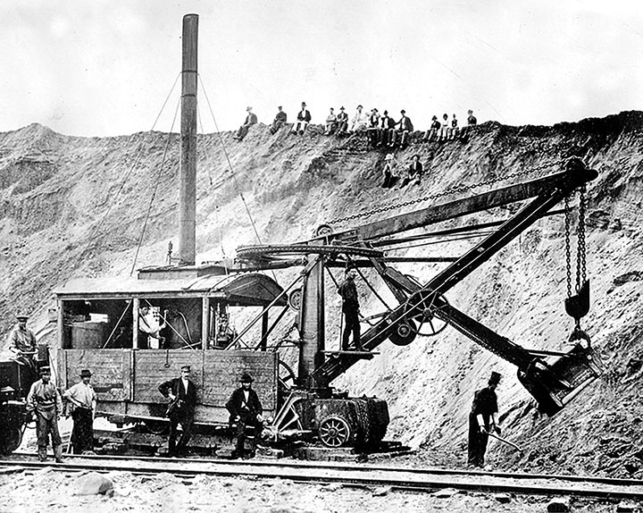
The Centre County Historical Society, located in State College, began a project in 2019 to build a model replica of Scotia. This model railroad is being built by several local model railroaders in HO scale; the platform is 8- x 12-feet. The Society has a collection of vintage photographs and maps of the Scotia operations and town of some 400 residents. Most of these photographs and maps are given in the book, The Story of Scotia by Henry M. Williams and edited by Betty F. Johnson (http://centrehistory.org). The vintage maps can also be seen on the Purple Lizard map: Scotia/Pennsylvania State Game Lands 176 (www.purplelizard.com). The modelers are using these photographs to build two models of the Otis-type steam excavators that were used at the Scotia Iron Works. I saw two photographs of this machine in The Story of Scotia. Always up for a challenge, I accepted what appeared to be a daunting task! This article describes the steps I took to complete the models.
Creating the Plans for My Scotia Steam Shovel Models
The steam shovels used at Scotia were patented by William Smith Otis in 1839. William was the cousin of Elisha Otis who invented the Otis elevator. I needed to create a plan for this shovel before any construction could begin. The only drawings I could find were from the patent found on the internet. The plan view had a scale of 4 inches = 16 feet which of course, is ¼ inch = 1 foot. I used this patent drawing to help me make a full-size drawing for my HO scale models. I would build both models at the same time doing the steps consecutively. This procedure allowed me to correct any errors made on the first model while performing the same step on the second.
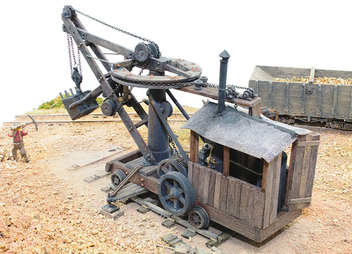
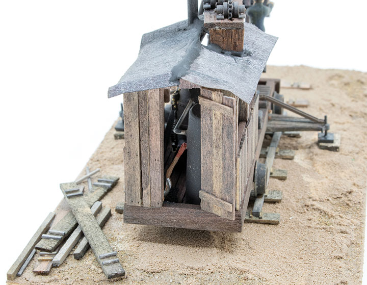
My plan for the models does not follow the Otis patent drawings exactly. The photograph of the Scotia steam shovel clearly shows that it was longer and had a roof. The added length is reflected in my drawing which allows for an onboard water tank, coal bin, and rear door. The wheel track of the excavator is 8 feet, almost twice the distance of standard gauge rail spacing. There is no record of how the machines were transported from Boston to Scotia. They were likely disassembled at the factory and the pieces shipped in railcars to Scotia where they were reassembled at the mines.
The Parts for My Scotia Steam Shovel Models
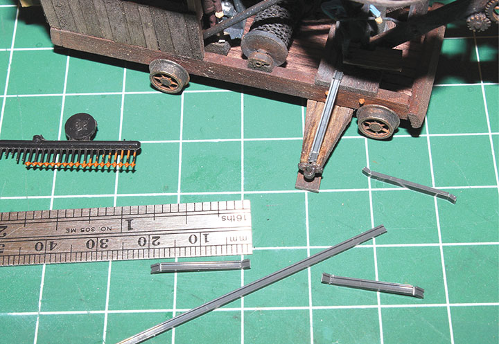
Before I joined the Scotia Model Re-creation Group, they had found a couple of Jordan Erie B-2 Steam Shovel kits, #303 online, and purchased them. The bucket in this kit is a close match to the one shown on the Otis drawing, so I assembled them for use on my models. The B-2 boom rigging pulleys also matched, so they too were retained and used. These were the only parts I could use from the Jordan kits. Commercially made white metal gears from Wild West Scale Model Builders #DP 32 were also purchased. The steam boiler and engine found in Woodland Scenics’ Steam Engine and Hammer Mill kit #D229 were a good match to the prototype, so I purchased those as well. 123Narrow gauge locomotive pilot wheels in 24-inch diameter were obtained from Precision Scale Company, #31937. The wheel track was increased to the required 8 feet by first parting the axle in the middle and then inserting the axle stubs of the wheels into the proper length of brass tubing. The chassis of the steam shovels were made by laminating 4x10 redwood boards for the floor, and then boxing them with 4x18 planks. The 5-foot diameter steam engine flywheels were scratchbuilt from large white metal gears and ABS plastic tubing.
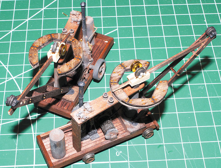
There are two different size sheaves on the excavator: 10- and 20-inch diameter. The smaller diameter sheaves guide the chain from a chain drum behind the steam engine to the 10-foot diameter boom swing gear. I turned these on a lathe from 1/8-inch polystyrene rod. A 0.020-inch axle hole was bored through the rod before sawing the individual sheaves off with a jeweler’s saw.
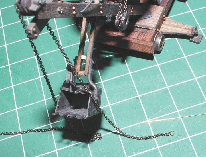
The 20-inch sheaves are on the tapered pylon that supports the swing gear, and on the boom itself. The sheaves on the boom are double sheaves. These sheaves guide the chain from the main chain drum that raises and lowers the dipper stick. All 20-inch sheaves were made by sandwiching a fiber washer used in the electronics fabrication industry, between two brass washers, and cementing the bundle with ACC. The washer holes were filled with epoxy and then re-bored to 0.032-inch, the bore size of the Tichy Train Group pillow blocks used (#8313). The main chain drum located directly behind the tapered pylon was made on my lathe using polystyrene rod and tubing. I had the tapered pylon 3D printed in plastic by a local firm. The chain I used has 27 links per inch.
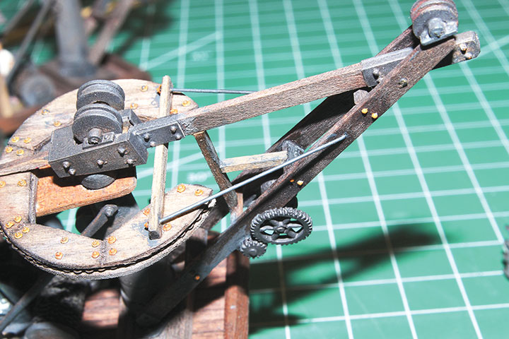
The dipper stick was moved to-and-fro on the boom by a rack and pinion. The drawings and photos of the earliest excavators were not clear on how this was made. The 3D patent drawing suggests that the linear gear (rack) is a linked chain. There is a pair of these, one under each arm of the dipper stick. I used the 27 links per inch chain for these on the models. I would surmise, however, that the manufacturers of these steam shovels used a roller chain for the rack and a spur gear for the pinion. The two pinions are on a shaft underneath the boom that is rotated by a large gear on the right side of the boom; a much smaller gear drives this large gear. The small gear shaft has a sheave on its left-boom-side end. That sheave is chain driven from the main chain drum on the chassis.
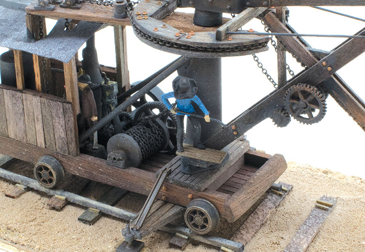
An engineer operated the steam shovel next to the steam engine, while a second operator stood on a small platform at the base of the pylon. He controlled a lever that locked or released the hinged flap under the bucket. There was likely a fireman on the excavator too.
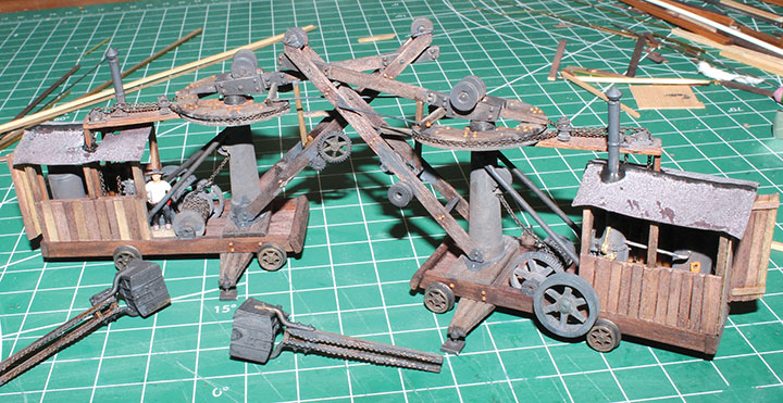
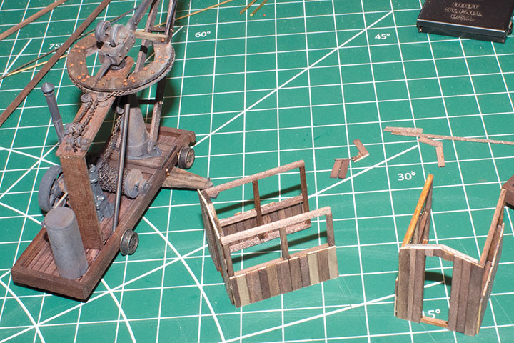
Assembling the Scotia Steam Shovel Models
Once all the small parts were made, they were put in place from inside-to-out. The chains were the last items to be placed. I did most of the arrangements dry before cementing the items down. All metallic and plastic parts were airbrushed with Floquil Grimy Black before gluing them in place. At the completion of the project everything was weathered with a mixture of 1 part India ink to 20 parts isopropyl alcohol; powdered pastels were also used.