In the November/December 2020 GAZETTE, I explained the criteria I use for selecting a model for a brass bashing project. I then worked through upgrading the drivetrain and adding details to a Balboa HOn3 model of a D&RGW C-19 class locomotive. When completed, the model will be a representation of D&RGW #340 in the mid-1940s.
In this issue I will continue this project from where I left off. Detailed information is presented here in the photo captions that follow.
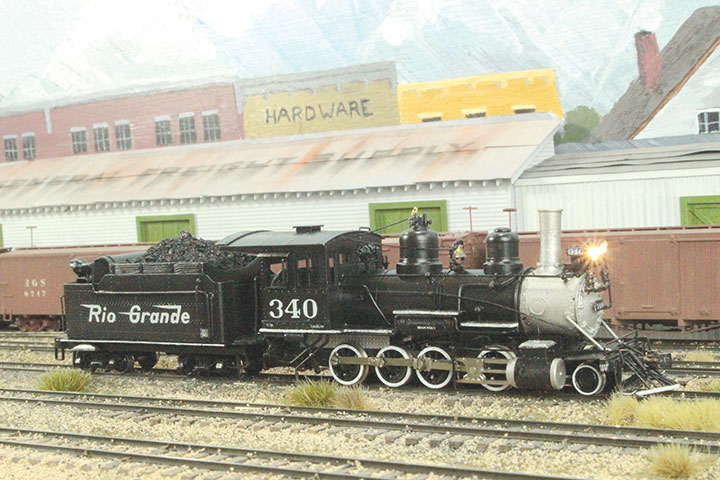
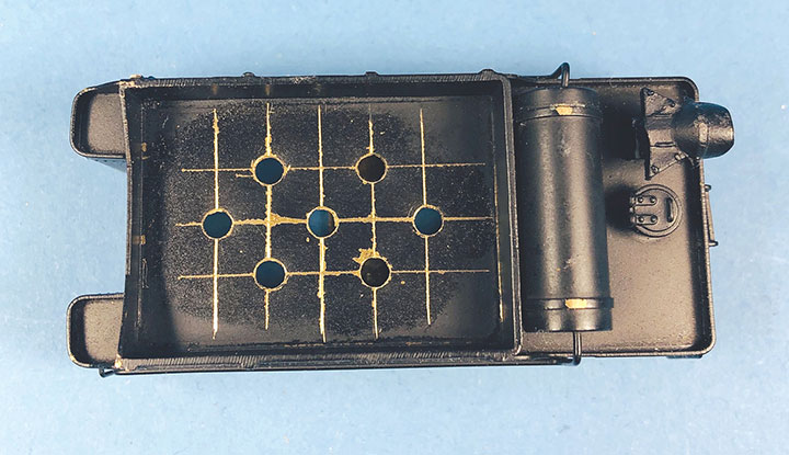
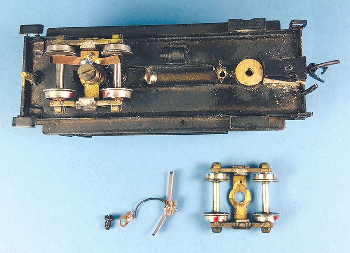
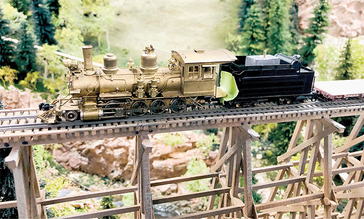
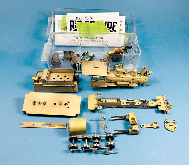
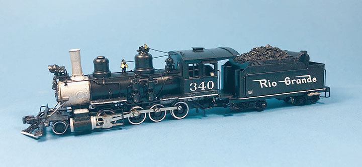
Freshly painted D&RGW #340 has been pulled out of the Ridgway Shops on the author’s layout and is ready for service. This model started as a box of parts from an eBay purchase, and with some work has been upgraded into a fine looking and running locomotive.I planned to install a sugar cube speaker inside the tender of #340, so I needed to add holes to let the sound out. The underside details, coal bunker construction and internal bracing of the tender dictated where I drilled the sound holes. There was a lot of bracing under the bottom of the tender floor and frame which would make drilling holes difficult. However, the coal bunker was a simple brass sheet and lacked bunker details, so I decided to drill holes in the bunker top. The speaker doesn’t care what size holes it has or how neat the pattern of holes is, but I like to create a professional look to my models. I’ve seen some really nice models where someone has drilled a mess of random holes that look absolutely terrible. To show some craftsmanship, I create a neat grid of holes. For #340, I used my calipers to measure the width of the coal bunker. I then divided that number in half and used my calipers to scratch a center line in the bunker. Working from each side, I closed my calipers by .200-inch and scribed a new line. I repeated this until I covered the tender top. Using the same technique, I scribed a series of lines in the opposite direction. In the end, I created a neat grid of lines to use as a pattern to drill the holes. I’ve tried using power tools to drill the holes, but have found that a pin vise gives me better control. I start by drilling #76 holes at the grid intersections because it allows me to accurately center the hole. I then make several passes at drilling these holes with progressively larger drill bits. When I’m satisfied with the holes, I use hand files to remove the burrs around the edges. When I’m done, I have a neat, professional looking grid of sound holes.On a typical brass model, the stock electrical pickup from the tender wheels must pass electricity from the axles through the side frames and then through the bolster to the tender frame. That creates two friction points that can oxidize or get dirty over time, eventually resulting in unreliable electrical pickup. To solve this problem, I always add tender pickups to my brass models. I create an axle wiper out of .008-inch phosphor bronze sheet for each truck. I reinforce the center portion with a small piece of PC board tie material. Through this reinforced section, I drill a hole to accept a 1mm screw. I drill and tap the truck bolster to recieve this screw, then attach this wiper with a screw versus soldering it to the bolster because it allows me to remove it to adjust the tension that the wiper presses against the axles. I then solder a short piece of 36 AWG wire to the wiper and solder a NWSL wire tab to the other end. I use this wire tab to screw the wire to the bottom of the tender frame. I use a screw connection for the pickup wire versus soldering because it allows me to make the truck more easily removable. Sometimes I get lucky and there is an existing screw to use, but usually (as in the case of #340) I will drill and tap the tender bottom for a pair of 2mm screws.With the DCC temporarily installed, I test run a locomotive on my layout. I need to work out all the potential problems before painting the model. This process can be frustrating but must be done. In my experience, intermittent shorts and electrical pickup problems are the most common. I found that one of the insulated tender wheels was intermittently touching the side frame on curves, and adding an insulated washer solved that problem. I also had an intermittent short between the tire on one of the insulated drivers and the locomotive frame. I had to remove the wheel from the axle to install a washer to keep the driver tire from touching the frame. Unfortunately, this required re-quartering the axle and re-tuning the drivetrain. The last problem was the pilot truck would derail. I made a custom lead weight for the pilot truck arm and ground the locomotive frame to allow it to pivot with the weight installed. After running the locomotive some more through challenging trackwork, and with cars in tow, I was eventually satisfied with its running.NOTE: When I install the DCC components for test running, I only install the minimum of electronics to get it to work. This would include the decoder, keep alive capacitor, power pickups and motor wires. I don’t bother adding lights at this stage since they would have to be removed for painting and likely would get broken in the process. I do prepare for the lights by drilling a #76 hole in the back of the headlight/taillight castings with a corresponding hole in the boiler and tender shell to route the wires. For #340, I also replaced the marker light castings with cored out marker lights from Precision Scale so that I could install SMLEDs in them. Below these marker lights, I drilled holes in the smokebox front for routing the wires into the boiler. After the model is painted, I will install the SMLEDs and lenses.While test running, I found that the pilot truck would pick the points on some turnouts causing the locomotive to derail. To solve this problem I decided to add weight to the pilot truck tab. The first step was to replace the screw on the pilot truck with a longer one that would be used to help mount a lead block on the pilot truck tab. I then fabricated a weight from a stick of lead that I bought from a fishing supply store. They sell lead ingots for casting fishing lures and weights. My pilot truck lead weight was then installed, and I re-tested the locomotive’s running performance on my layout.With the locomotive running well, it was time to paint it. I stripped the model down to its basic components and removed the electronics. The small parts were taped to business cards and labeled. The wheel treads and electrical surfaces where covered with tape to protect them. The cylinder guides were protected with heat shrink tubing and wood plugs added to the cylinder holes. I ran all of the brass pieces through my sandblasting booth to remove any paint, oxide and excess solder. The brass pieces were then cleaned in my ultrasonic cleaner with plain warm water. I also cleaned the oil off the drivers and gearbox by cleaning them in my ultrasonic cleaner with some soap added to the water. Finally, the model was ready for painting as shown in this photo. For an exhaustively detailed article on how I paint my models, see the 2009 issue of the HOn3 Annual.Since the stock model best represents #340 in the mid 1940s, and I model the early 1940s, I decided to paint the locomotive as if it was freshly out of the paint shops. The Friends of the Cumbres & Toltec online photo library was very helpful for getting all the details correct. I used Scalecoat paint for #340 and started with painting the smokebox, firebox and cylinders with Scalecoat Graphic and Oil. I then masked these areas and sprayed the rest of the model with Black. Using White paint, I brush painted the running board, tender frame and pilot edges. Thinfilm Decal set HOn-01, D&RGW NG White Set had all the correct lettering including the mismatched and odd sized tender lettering unique to the real #340. Once the decals had set, I sprayed the entire model with a 50:50 mix of Scalecoat Gloss and Satin clear finish.By far, the most frustrating and challenging part of brass bashing is getting the model to run again after it has been painted. This task is further complicated by the care needed to protect the paint job from all of the additional handling. For this model, I found that even though it ran perfectly before painting, the drivetrain was now binding after re-assembly. I ended up adjusting the valve gear and drivers until the chassis would roll freely when pushed across a sheet of glass again. Once that was accomplished, I installed the gear tower and motor, and test ran the mechanism in both directions and at a variety of speeds.NOTE: I always work over a sheet of paper towel on my workbench. I find it keeps my work surface clean and is helpful for seeing small parts, as I’m working on a model. It’s also very helpful for protecting a painted model’s finish. I change it often. While re-tuning the drivetrain, the paper towel collected excess oil and protected the chassis paint as you can see in this photo.Because this model is so small, I had to pack the Soundtraxx TSU-1100 decoder, TCS KA2 current keeper and Litchfield Station sugar cube speaker, in the tender. The model didn’t have room for micro connectors between the locomotive and tender, so I simply hard wired them together. The wires running between the locomotive and tender were routed through a short piece of heat shrink tubing. Later, when I was satisfied with the install, I shrunk this tubing around the drawbar. Using this method helps keep the wires under control with this hard wired installation. I also added a lead block in the remaining void in the tender. I find that HOn3 tenders need additional weight in the tenders to help with electrical pickup.I finished the model by installing 0602 SMLEDs in the headlight and backup light. Both of these lights had a MV Products #173 lens with the foil removed added to them. I also installed 0402 SMLEDs in the marker lights that I had installed on the smokebox front. A coal load was made for the bunker using foam and real RGS coal. I demonstrated this technique in my Rico Coal Pocket article in the September/October 2020 GAZETTE. Finally, clear plastic was installed behind the cab windows and the model fully assembled. After it gets some run time in, and I’m certain that it doesn’t need any more tuning, I’ll weather the model to make it look less pristine.The final step I take when I’m working on a brass model is to fine tune the DCC settings using the JMRI DecoderPro software. Along with setting the locomotive number, I like to adjust the individual sound volumes, chuff timing, add some momentum and adjust the speed curve. I find this helps smooth out the running performance to where I like it. Sometimes I also adjust the CVs for controlling the additional lighting functions. I use an NCE Power Cab controller, my laptop and a test track to accomplish this.It is a lot of work to brass bash an older model into something more contemporary. Admittedly, it can be frustrating getting these older models to run well, but with persistence the results can be very rewarding. Turning a once sub-standard model into a show piece can be a lot of fun and nothing beats the “I did it” feeling when you see your new jewel running down the rails on your layout. I hope this pair of articles has given you the encouragement, examples and inspiration to bring out your inner brass bashing skills to start your own project.