The On30 switching layout I described in the July/August 2020 Gazette has seven hand-laid turnouts. Another On30 layout I am working on has twenty-three turnouts. To save time, I used Micro-Engineering (ME) flex-track and turnouts in most places on my new layout. After all, given my age, I wanted to live to see that layout in operation. Commercial turnouts cost $20.00 to $25.00 each, but to my dismay, I discovered that commercial turnout controllers are just about as expensive. So in order to save money and challenge my ingenuity, I decided to devise a turnout control system of my own that would be fairly simple, highly reliable, and above all, less costly. What I came up with fits those requirements and allows me to throw points and route electricity for about $8.00 per turnout, linkages included. Both of my layouts use this system and I have found it to be totally reliable over years of operation. If you decide to try my system, I recommend mass producing the units, maybe a dozen at a time. You can work more efficiently this way and later on, as your layout progresses and you install more turnouts, all you need to do is go the shelf, pick up the finished components, and do a 20–30 minute installation.
Turnout Preparation
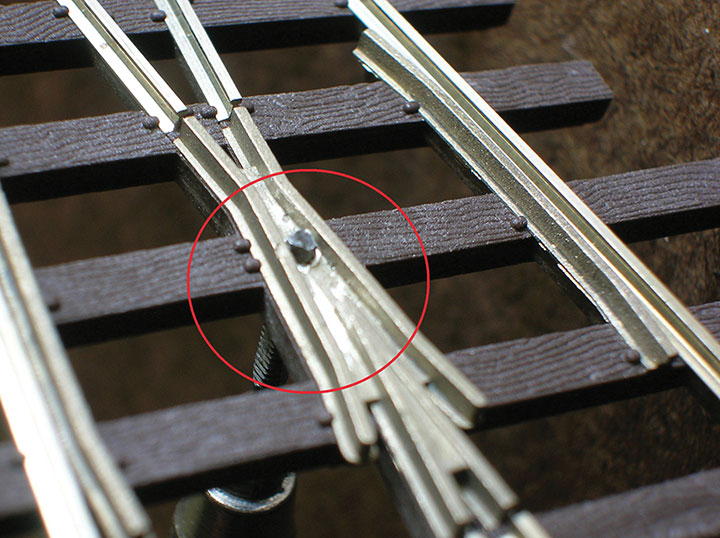
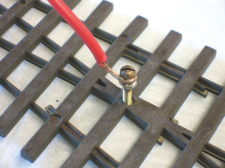
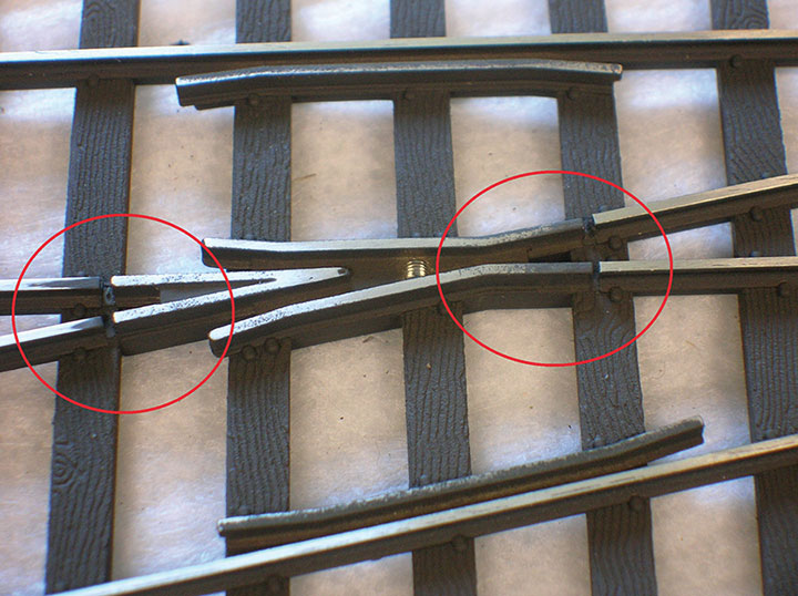
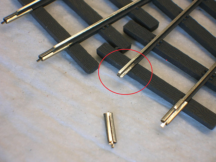
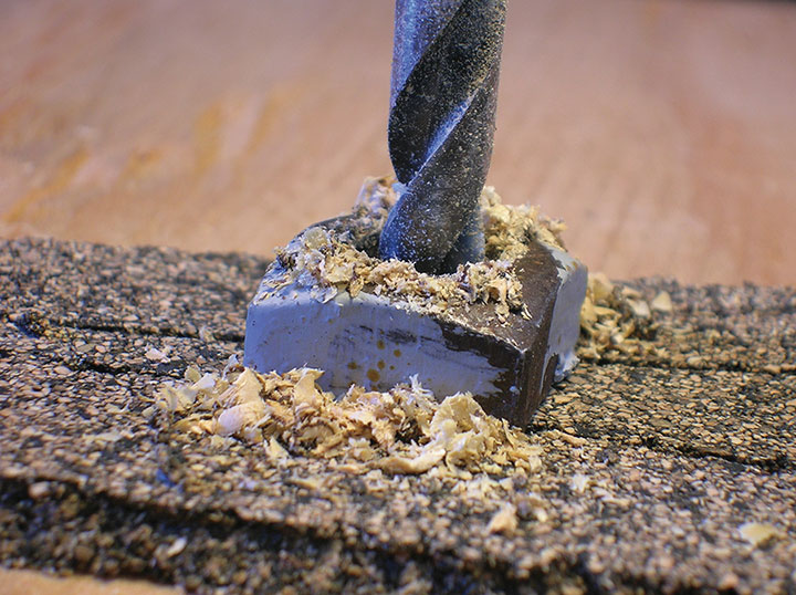
I have found that ME turnouts can use some preparation on the workbench to improve their function and appearance, and make them easier to install. The turnouts come with a dead frog, which is all right for long-wheelbase locomotives, but if you are running Porters, a gas-mechanical, or some other short-wheelbased “critter,” every bit of rail needs to be available for electrical pickup in order to get reliable operation. ME suggests soldering a frog feeder into the hole in the bottom of the frog, but when I tried to do this, the result was usually a cold solder joint or melted ties, and most often, both. As a result, I devised a procedure that connects a frog lead without soldering to the turnout. Some other simple operations can improve the turnouts as well. Follow Photos 1-4 to see what I did.
Constructing the Point Movers
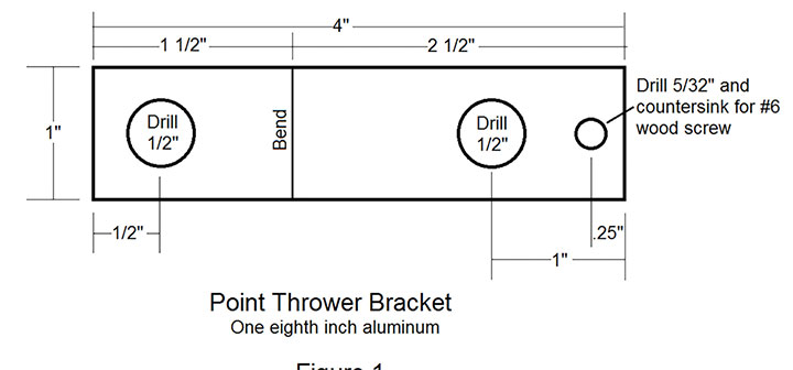
You will need some one inch wide 1/8-inch-thick aluminum strip, available at your local hardware store in three-foot lengths. One length will make nine of the brackets described here. Also required are DPDT toggle switches, some fender washers (a washer with an outside diameter much larger than its hole), some brass strip, music wire, brass tubing and wood screws. Cut, drill, and bend the aluminum strip to the dimensions shown in Figure 1. I used a small metal-bending brake for the bend, but a sturdy vise and careful use of a hammer will do the job.
The DPDT switch moves and holds the points. Only one set of contacts is needed to control frog polarity, but the extra set on a DPDT switch may come in handy some day. I like DPDT switches that are screwed together because they can be easily taken apart to slot the toggle handle. This may not be necessary, but I did it to avoid stressing the switch while sawing the slot. If you take it easy, or use a slotting method less aggressive than a hacksaw, you may be able to leave the switch intact. If you do take the switch apart, put it back together again before you glue in the extension strip or you will not be able to get the handle through the hole in the top of the switch.
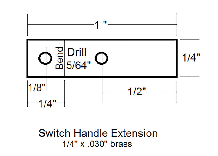
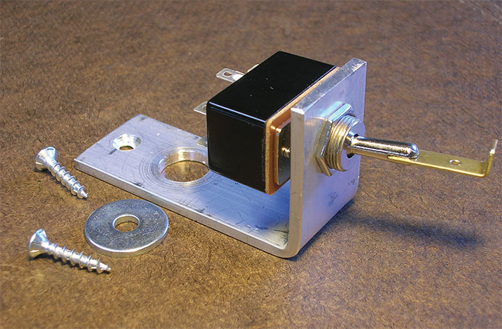
A one-inch strip of brass a quarter-inch wide and .030-inch thick is used to extend the switch handle for more mechanical movement when throwing the points. See Figure 2 for the dimensions. In my switches, the handle is a form of pot metal and will not take solder, so the extension strip is secured in the slot with ACC. If you make the extension strip fit snugly into the slot to begin with, ACC will produce a totally adequate bond. Test the joint by applying force by hand. (Over many years of use, I have had just one of these joints fail, but it was probably because the slot was wider than it should have been.) With the extension strip installed, attach the switch to the aluminum bracket as shown in the photos and place another drop of ACC between nuts and bracket to make sure things don’t work loose. Photo 5 shows the assembled components.
Installing the Turnout and Controller
I use cork roadbed over plywood for my trackwork, but the installation procedure is similar for other materials. Follow Photos 6–7 to see the process. After locating the turnout on the roadbed and drilling the frog feeder hole, screw the frog wire into the bottom of the turnout as in Photo 2. I first coat the screw tip with some anti-oxidation compound to insure a good, permanent electrical connection with the turnout. You can get this in the electrical department of the same hardware store where you got the aluminum strip.
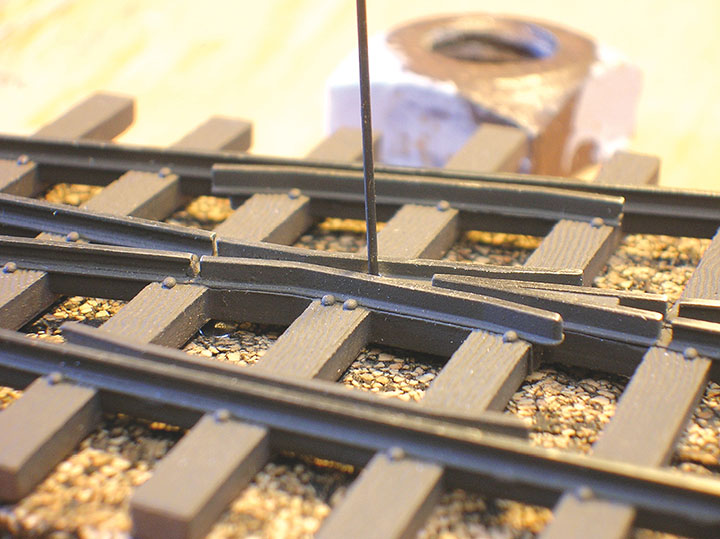
The turnout is thrown with a piece of .025-inch music wire passing down through the roadbed in a 1/16-inch diameter brass tube. The music wire is a fairly loose fit in the tube to reduce friction, and make bending the wire to fit the hole in the throw bar a little less critical. The relationship between point thrower position under the track (which may be dictated by benchwork constraints) and the position you want the control knob to be in for a given position of the turnout, will determine on which side of the throw bar the tube is placed. For example, I standardized my turnouts so the knob is pushed in when the far track is selected, and out when the near track is selected. Once you figure this out, Photo 8 illustrates the installation.
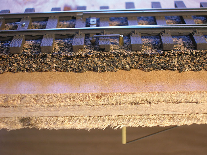
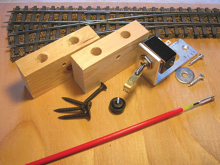
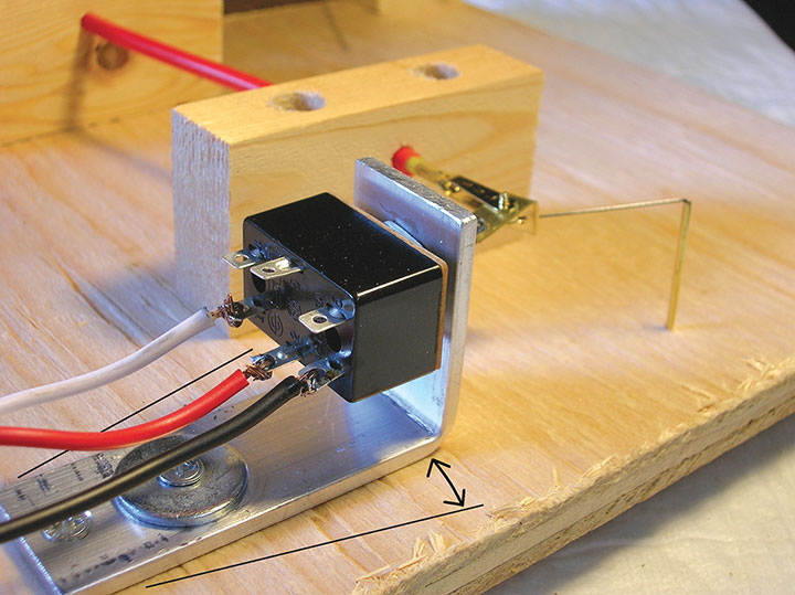
Photo 9 shows the components of the turnout controller ready to install. Photo 10 shows a completed installation and describes the adjustment procedure. Getting a helper to assist with the adjustment can save your knees and back.
Control Linkage
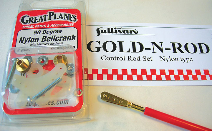
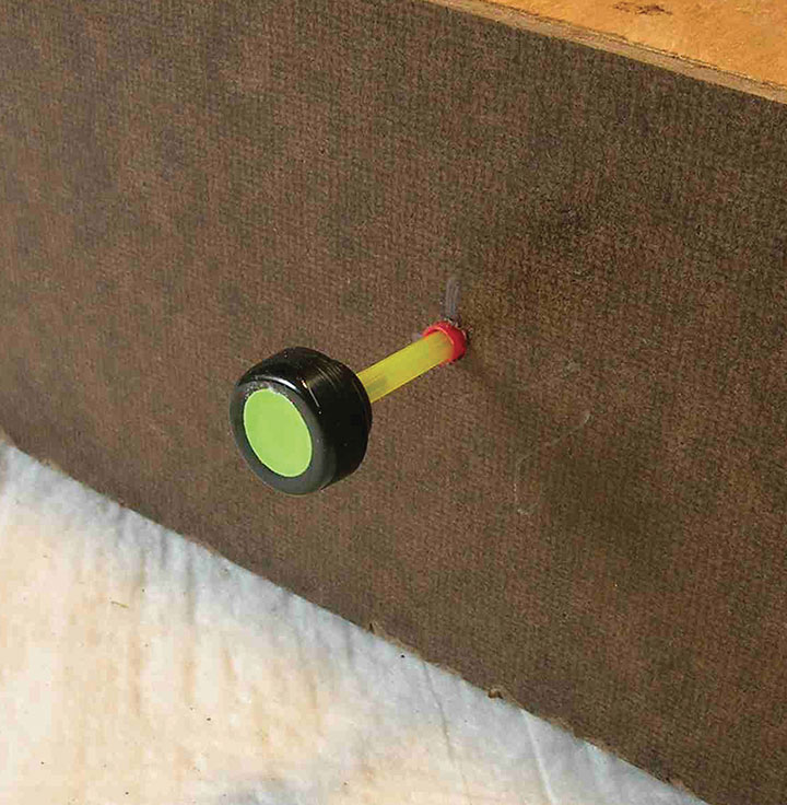
Turnout control is from the edge of the layout by means of the telescoping nylon tubing used by RC airplane hobbyists to operate control surfaces on their planes. See Photo 11 for a sample of the materials available. Photo 12 shows how additional bell-crank components can be used in tight situations.
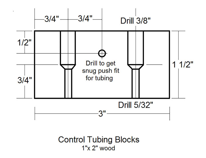
Unless the tubing run is very short, two wood blocks made of 1- x 2-inch stock secure the outer guide tube. See Figure 3 for the dimensions of these blocks. The hole for the tubing should give a nice tight fit for the tube to keep it from working back and forth on its own, but you still need to be able to push the tubing through it. Again, I recommend mass producing these blocks for convenience later.
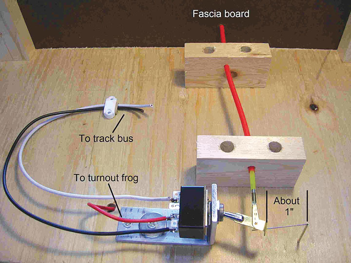
Secure one block near the point mover under the turnout. Use just one screw to begin with. Push the outer control tube through the second block that will be placed behind the fascia board. Drill an appropriately placed hole in the fascia board, insert the outer tube through it, and push the far end of the tube through the block near the controller, leaving about an inch of space between it and the hole in the extension handle. Now position the other block a few inches from the back of the fascia board in a way that directs the tubing through the fascia at a right angle, and screw it to the benchwork.
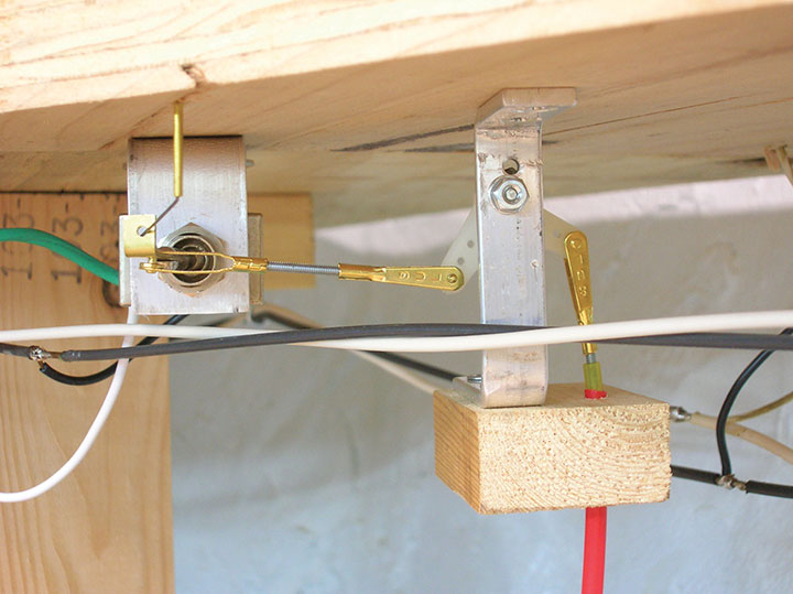
Screw a piece of the 2-56 threaded rod that comes with the tubing into one end of the inner tubing, clip a clevis to the switch handle extension, thread the inner tubing through to the point mover, and screw the threaded rod into the clevis. Leave about half a dozen or so threads visible between the tube and the clevis to allow minor adjustments in cable length later. Tweak the wood block back and forth on its single screw to optimize alignment between the control tubing and the hole in the handle extension, and secure the block with a second screw. Again, refer to Photo 13 to see a completed installation as viewed from below. Photo 14 shows how it looks to the operator.
Now all that needs to be done is to make the electrical connections and you are finished. The frog lead goes to one of the center posts on the switch, and the track bus leads go to the side posts. Make sure you have the bus wires going to the proper posts for correct frog polarity before soldering.
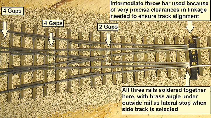
Three-Way Stub Turnout
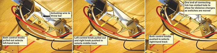
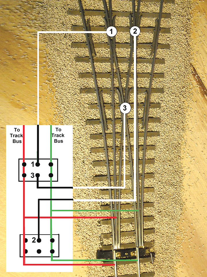
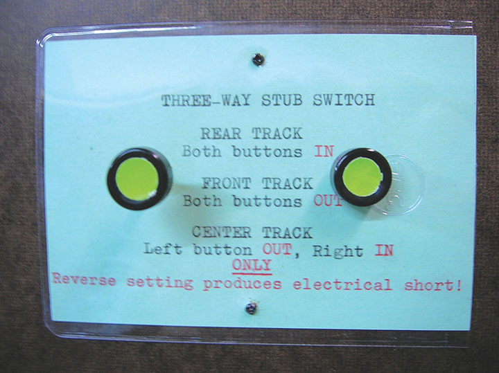
A special adaptation was needed for a hand-laid three-way stub turnout on my layout. This application uses two of the controllers just described. Both controllers are fastened to a 1- x 1/8-inch aluminum strip as a foundation, which is in turn screwed to the underside of the benchwork. The controllers are positioned facing each other so that a brass link can be connected between the handle extensions using the cable clevises as pivot points. The pivot holes in the link bar are two inches apart. The rail movement wire is actuated from the center of this link. When both controllers are thrown in the same direction, either forward or backward, the side tracks are selected. When the controllers are set in opposite directions, the center track is aligned. See Photos 15 and 16 for the details. Wiring is illustrated in Photo 17. With this setup, only one of the two possible settings for the center track will work electrically, but this is just a matter of getting into the habit of using the right combination. A notice on the fascia board is a reminder of the correct setting. See Photo 18.